In the electrical industry, many different types of diagrams are used. Each type of diagram will represent certain criteria of the designer.
This section will introduce the types of diagrams as well as the relationships between them.
3.1. Schematic diagram.
A schematic diagram is a type of diagram that shows the operating principles of an electrical circuit or network. It explains and helps the technician understand the operation of the electrical circuit or network. In other words, a schematic diagram uses electrical symbols to represent the relationships in connecting and operating an electrical system or a part of an electrical system.
The schematic diagram is allowed to be arranged in a way that makes it easy to draw the circuit, easy to read, and easy to analyze. The schematic diagram will be drawn first when designing an electrical circuit or network. From this diagram, other diagrams will be drawn (equipment layout diagram, wiring diagram, etc.).
Schematic diagrams can be presented horizontally or vertically. When presented horizontally, the successive components of the circuit are drawn in order from top to bottom. When presented vertically, the order is from left to right.
A diagram that only shows the electrical connections of the elements in the circuit without showing their actual installation location or arrangement.
The schematic diagram used to study the working principle of the circuit is the basis for building the installation diagram.
Figure 1.1 shows the electrical relationship between the power source, fuse, socket, switch, and light bulb.
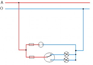
Figure 1.1. Example of schematic diagram
3.2. Floor plan and location diagram.
a. Floor plan.
Is a diagram showing the dimensions of a building (factory, room, etc.) from a top-down view.
b. Location map.
Based on the floor plan, people arrange the location of the equipment with full dimensions, called a location plan. The symbols used in the location plan are the symbols used in the floor plan.
The site diagram clearly shows the location and installation of the circuit elements. The site diagram is used to estimate materials and install electrical equipment.
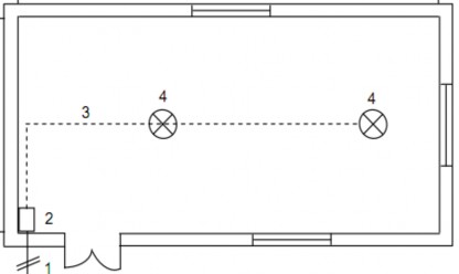
Figure 1.2. Example of a location diagram
3.3. Wiring diagram.
It is a type of diagram that describes the specific wiring scheme of an electrical circuit or network derived from a schematic diagram.
Wiring diagrams can be drawn independently or combined on the site plan. The contractor will read this plan to assemble in accordance with the designer's spirit.
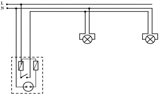
Figure 1.3. Example of wiring diagram
Review questions
1. Describe the general concept of electrical installation techniques?
2. What are some commonly used symbols in electrical systems?
3. Describe the types of diagrams in electrical systems?
Suggested answer:
The above are theoretical questions, helping students review and master the basic knowledge of electrical installation techniques.
Students can present the steps to prepare for electrical installation, know the symbols on electrical drawings and read the types of diagrams used in installation.
LESSON 2:
INSTALLATION OF POWER SUPPLY SYSTEMS FOR BUILDINGS AND APARTMENT COMPLEXES
Introduce:
Power lines for buildings and apartment complexes must always operate stably to maintain power supply for human activities as well as systems in the building, so the installation of power supply systems for buildings and apartment complexes must be carried out according to the correct techniques and ensure safety when put into operation. Lesson 2 in this module aims to provide learners with skills and methods for installing power lines for buildings.
Target:
- Present the content of electrical installation work organization.
- Describe commonly used symbols in diagrams.
- Understand the diagrams used for electrical installation.
- Have full capacity, sense of responsibility and industrial style.
1. General concept of cable installation.
Objective: Read design documents, know how to preserve and transport cable drums.
1.1. Design documents.
The lines are built according to the design. The design documents include:
- Plans and cross-sections of cable installations, drawings of other external cable routes indicating all cross-sections and cables located close together and underground structures. These drawings indicate distances to the nearest buildings or other points in the area, or signs (landmarks) to the cable line location, and installation depth in the cable tunnel.
- Construction drawings of cable tunnels, cable ducts, cable ditches and cable wells with full necessary dimensions (in case of laying cables in cable tunnels and cable ducts).
- The cable book clearly indicates the cable code, installation method and characteristics of each line (e.g. cable length, location, voltage and cross-section of cable; marking of installation location and type of cable junction box).
- List of cables, junction boxes, materials, components and details.
1.2. Storage and transportation of cable drums.
1.2.1. Storage.
- Preservation method.
Cable drums and cable reels must be protected in a covered building. The drums must be arranged according to code, voltage and cross section so that they can be easily retrieved.
Protection of uncovered cable drums should not exceed one year: then the sides of the cable drums should be raised.
The two ends of the cable reel must be sealed to prevent moisture.
The inner end of the cable reel is brought out and the outer end is clamped together with the inner end to fix it on the drum cheek. This arrangement is convenient for testing and drying the cable.
- Cable storage.
When arranging cables by code, we arrange them in alphabetical order or in numerical order from smallest to largest or vice versa depending on each person's arrangement.
Arrange by voltage depending on the number of each type of cable we use, but we must arrange them in order.
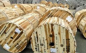
Fig. 2.1. Cable drums
1.2.2. Transportation.
- Shipping method.
When laying cables outside the house, the cable drums must be transported to the installation site in a way that does not obstruct traffic. Cable lengths under 25m are best transported to the installation site by rolling the cable drum. To avoid the cables from coming loose from the drum, the drums must be tied in at least 4 places.
When lifting and lowering wire rolls, mechanical means must be used, using cable lifting machines, crane trucks or winches.
Transporting cables over long distances requires the use of trucks or transport on specialized transport equipment, using cars or tractors.
The structure of the conveying device allows the cable to be laid directly from the cable lot placed on the conveying device.
For short distance transport, a cargo handling vehicle can be used. In this case, lifting and lowering the cable drums is much simpler.
Additionally, the following shipping methods are allowed:
a) Rolling the cable drum directly on the ground.
+ Manual rolling when the cable drum is directly rolled over a short distance (100 ÷ 200m) and when the cable drum has defects, the outer rings are not less than 100mm from the edge of the drum cheek, allowing rolling over this short distance.
+ Use winch and rope tied directly to the steel shaft through the wire roll's frame to roll small and medium-sized cable rolls over a not-so-large distance (up to 1km) within the installation route.
b) Transport the cable drum placed on a steel plate, using a winch or tractor when crossing weak, muddy ground.
When lifting and transporting cables, there must be an experienced person to monitor and observe.
Do not push the cable drum from cars, railway carriages, transport machinery as well as dry floors, on platforms to the ground because when pushed and dropped, the cable drum may break, leading to damage to the cable sheath.
When there is no crane or crane truck, the lifting and lowering of cable drums is done by placing sturdy wooden planks as slides with a slope of 1: 4 for the cable drums to slide slowly to the ground. To stop the cable drum from rolling and sliding quickly, use ropes or winches. To pull the cable drum from the ground to the truck, use a winch or rope.
Before rolling, carefully inspect the cable drum to see if the panels that are tightly attached to the shell are loose or damaged.
When rolling, the cable drum can only rotate in the direction of the arrow marked on the drum cheek (Figure 2.2).
When rolling, rolling the cable drum on weak ground, wooden planks must be lined.
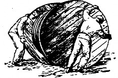
Figure 2.2. Rolling the cable drum
1.3. Minimum allowable cable bend radius.
- When installing cables, ensure that the bending radius of the cable or cable core is proportional to its outer diameter.
- The bends or branches of the cable ladder and cable support must ensure the minimum bending radius of the cable according to the following table:
Table 1: Table of minimum cable bending radius regulations
Insulation
Covering | Diameter | Radius of curvature |
Maybe you are interested!
-

 Car body electrical practice - 8
zt2i3t4l5ee
zt2a3gs
zt2a3ge
zc2o3n4t5e6n7ts
If the voltage is out of specification, replace the wire or connector.
If the voltage is within specification, install the front fog light relay and follow step 5.
Step 5 Check the front fog light switch
- Remove the D4 connector of the fog light switch
- Use a multimeter to measure the resistance of the front fog light switch.
Measurement location
Condition
Standard
D4-3 (BFG) -D4-4 (LFG)
Light switchFront Fog OFF
>10kΩ
D4-3 (BFG) -D4-4 (LFG)
Front fog light switchON
<1 Ω
- Standard resistor
D4 connector is located on the combination switch assembly.
If the resistance is out of specification, replace the combination switch (the fog light switch is located in the combination switch).
If the resistance is within specification, follow step 6.
Step 6 Check wiring and connectors (front fog light relay-light selector switch)
- Disconnect connector D4 of the combination switch assembly
- Use a voltmeter to measure the voltage value of jack D4 on the wire side.
Measurement location
Control modecontrol
Standard
D4-3 (BFG) - (-) AQ
TAIL
11 to 14 V
D4 connector for the wiring of the combination switch assembly
If the voltage does not meet the standard, replace the wire or connector.
If the voltage is within standard, there may have been an error in the previous measurements.
Step 7 Check the front fog lights
- Remove the front fog light electrical connector.
- Supply battery voltage to the fog lamp terminals
Jack 8, B9 of front fog lamp on the electrical side
blind first.
Power supply location
Terms and Conditions
Battery positive terminal - Terminal 2Battery negative terminal - Terminal 1
Fog lightsbefore morning
- If the light does not come on, replace the bulb.
If the light is on, re-plug the jack and continue to step 8.
Step 8 Check wiring and connectors (relay and front fog lights)
- Disconnect the B8 and B9 connectors of the front fog lights.
- Use a voltmeter to measure voltage at the following locations:
Measurement location
Switch location
Terms and Conditions
B8-2 - (-) AQ
Electric lock ON TAIL size switchFog switch ON
11 to 14 V
B9-2 - (-) AQ
Electric lock ONTAIL size switch Fog switch ON
11 to 14 V
B8 and B9 connectors on the front fog lamp wiring side
Voltage is not up to standard, repair or replace the jack. If up to standard, there may have been an error in the measurement process.
2.2.4. Procedure for removing, installing and adjusting fog lights 1. Procedure for removing
- Remove the front inner ear pads
Use a screwdriver to remove the 3 screws and remove the front part of the front inner ear liner
-Remove the fog light assembly
+ Disconnect the connector.
+ Use a screwdriver to remove 3 screws to remove the fog light cover
2. Installation sequence
-Rotate the fog lamp bulb in the direction indicated by the arrow as shown in the figure and remove the fog lamp from the fog lamp assembly.
-Rotate the fog light bulb in the direction indicated by the arrow as shown in the figure and install the light into the fog light assembly.
- Use a screwdriver to install the fog light cover
-Install the electrical connector
Attention: Be careful not to damage the plastic thread on the lamp assembly.
- Install the front inner ear pads
Use a screwdriver to install the front inner bumper with 3 screws.
3. Prepare the vehicle to adjust the fog light convergence. Prepare the vehicle:
- Make sure there is no damage or deformation to the vehicle body around the fog lights.
- Add fuel to the fuel tank
- Add oil to standard level.
- Add engine coolant to standard level.
- Inflate the tire to standard pressure.
- Place spare tire, tools and jack in original design position
- Do not leave any load in the luggage compartment.
- Let a person weighing about 75 kg sit in the driver's seat.
4. Prepare to check the fog light convergence
a/ Prepare the vehicle status as follows:
- Place the car in a dark enough place to see the lines. The lines are the dividing line, below which the light from the fog lights can be seen but above which it cannot.
- Place the car perpendicular to the wall.
- Keep a distance of 7.62 m between the center of the fog lamp and the wall.
- Park the car on level ground.
- Press the car down a few times to stabilize the suspension.
Note: A distance of approximately 7.62 m is required between the vehicle (fog lamp center) and the wall to adjust the convergence correctly. If the distance of 7.62 m cannot be achieved, set the correct distance of 3 m to check and adjust the fog lamp convergence. (Since the target area varies with the distance, please follow the instructions as shown in the figure.)
b/ Prepare a piece of thick white paper about 2 m high and 4 m wide to use as a screen.
c/ Draw a vertical line through the center of the screen (line V).
d/ Set the screen as shown in the picture. Note:
- Keep the screen perpendicular to the ground.
- Align the V line on the screen with the center of the vehicle.
e/Draw the reference lines (H, V LH and V RH lines) on the screen as shown in the figure.HINT:
Mark the center of the fog lamp on the screen. If the center mark cannot be seen on the fog lamp, use the center of the fog lamp or the manufacturer's name mark on the fog lamp as the center mark.
H line (fog light height):
Draw a line across the screen so that it passes through the center mark. Line H should be at the same height as the center mark of the fog light bulb.
Line V LH, V RH (center mark position of left fog lamp LH and right fog lamp RH):
Draw two lines so that they intersect line H at the center marks.
5. Check the fog light convergence
a/ Cover the fog lamp or remove the connector of the other side fog lamp to prevent light from the unchecked fog lamp from affecting the fog lamp convergence test.
b/ Start the engine.
c/ Turn on the fog lights and make sure that the dividing line is outside the standard area as shown in the drawing.
6. Adjust the fog light convergence
Use a screwdriver to adjust the fog light to the standard area by turning the toe adjustment screw.
Note: If the screw is adjusted too far, loosen it and then tighten it again, so that the last rotation of the light adjustment screw is clockwise.
3. Self-study questions
1. Describe the operating principle of the lighting system with automatic headlight function
2. Describe the operating principle of the lighting system with the function of rotating headlights when turning
3. Draw diagram and connect lighting system on Hyundai Porter car
4. Draw diagram and connect lighting system on Honda Accord 1992
5. Draw the lighting circuit on a 1993 Toyota Lexus
LESSON 3 MAINTENANCE AND REPAIR OF SIGNAL SYSTEM
I. IMPLEMENTATION GOAL
After completing this lesson, students will be able to:
- Distinguish between types of signals on cars
- Correctly describe common symptoms and suspected areas causing damage.
- Connecting signal circuits ensures technical requirements
- Disassemble, install, check, maintain and repair the signal system to ensure technical requirements.
- Ensure safety in work and industrial hygiene
II. LESSON CONTENT
1. General description
The signal system equipped on cars aims to create signals to notify other vehicles participating in traffic about the vehicle's operating status such as: stopping, parking, braking, reversing, turning...
Signals are used either by light such as headlamps, brake lights, turn signals….. or by sound such as horns, reverse music….
Just like the lighting system. A signal system circuit usually consists of: battery, fuse, wire, relay, electrical load and control switch. Only some switches of the signal system are on the combination switch. The switches of other signals are usually located in different locations such as in the gearbox or brake pedal……
2. Maintenance and repair
2.1. Turn signals and hazard lights
The installation location of the turn signal is shown in Figure 3.1. The turn signal control switch is located in the combination switch under the steering wheel. Turning this switch to the right or left will make the turn signal turn right or left.
The hazard light switch is used when the vehicle has a problem while participating in traffic. When the hazard light switch is turned on, all the turn signals on the vehicle will light up at a certain frequency. The hazard light switch is usually placed separately from the turn signal switch (some old cars integrate the hazard and turn signal switches on the same combination switch cluster).
Figure 3.1 Turn signal switch Figure 3.2 Hazard switch
The part that generates the flashing frequency for the lights is called a turn signal relay. The turn signal relay usually has 3 terminals: B (positive power supply); E (negative power supply); L (providing the turn signal switch to distribute to the
lamp)
2.1.1. Circuit diagram
To generate the frequency for the turn signal, a turn signal relay is used in the turn signal circuit. The current from the turn signal relay will be sent to the turn signal switch assembly to distribute the current to the turn signal lights for the driver's purpose.
Figure 3.3. Schematic diagram of a turn signal circuit without a hazard switch
1. Battery; 2. Electric lock; 3. Turn signal relay; 4. Turn signal switch; 5. Turn signal lamp; 6. Turn signal lamp; 7. Hazard switch
Figure 3.4 Schematic diagram of turn signal circuit with hazard switch
1. Battery; 2. Combination switch cluster; 3. Turn signal;
4. Turn signal light; 5. Turn signal relay
Today's cars no longer use three-pin turn signal relays (B, L, E) but use eight-pin turn signal relays (figure 3.5) (pin number 8 is used for hazard lights).
For this type, the current supplying the turn signal lights is supplied directly from the turn signal relay to the lights.
div.maincontent .p { color: black; font-family:"Times New Roman", serif; font-style: normal; font-weight: normal; text-decoration: none; font-size: 14pt; margin:0pt; } div.maincontent p { color: black; font-family:"Times New Roman", serif; font-style: normal; font-weight: normal; text-decoration: none; font-size: 14pt; margin:0pt; } div.maincontent .s1 { color: black; font-family:"Times New Roman", serif; font-style: normal; font-weight: normal; text-decoration: none; font-size: 13pt; } div.maincontent .s2 { color: black; font-family:"Times New Roman", serif; font-style: italic; font-weight: normal; text-decoration: none; font-size: 14pt; } div.maincontent .s3 { color: black; font-family:"Times New Roman", serif; font-style: normal; font-weight: normal; text-decoration: none; font-size: 14pt; } div.maincontent .s4 { color: black; font-family:"Times New Roman", serif; font-style: normal; font-weight: normal; text-decoration: none; font-size: 13pt; } div.maincontent .s5 { color: black; font-family:"Times New Roman", serif; font-style: normal; font-weight: normal; text-decoration: none; font-size: 13pt; vertical-align: 1pt; } div.maincontent .s6 { color: black; font-family:"Times New Roman", serif; font-style: normal; font-weight: normal; text-decoration: none; font-size: 11pt; } div.maincontent .s7 { color: black; font-family:"Times New Roman", serif; font-style: normal; font-weight: normal; text-decoration: none; font-size: 14pt; vertical-align: -9pt; } div.maincontent .s8 { color: black; font-family:"Times New Roman", serif; font-style: normal; font-weight: normal; text-decoration: none; font-size: 11pt; } div.maincontent .s9 { color: #008000; font-family:"Times New Roman", serif; font-style: normal; font-weight: normal; text-decoration: none; font-size: 14pt; } div.maincontent .s10 { color: black; font-family:"Times New Roman", serif; font-style: italic; font-weight: normal; te
Car body electrical practice - 8
zt2i3t4l5ee
zt2a3gs
zt2a3ge
zc2o3n4t5e6n7ts
If the voltage is out of specification, replace the wire or connector.
If the voltage is within specification, install the front fog light relay and follow step 5.
Step 5 Check the front fog light switch
- Remove the D4 connector of the fog light switch
- Use a multimeter to measure the resistance of the front fog light switch.
Measurement location
Condition
Standard
D4-3 (BFG) -D4-4 (LFG)
Light switchFront Fog OFF
>10kΩ
D4-3 (BFG) -D4-4 (LFG)
Front fog light switchON
<1 Ω
- Standard resistor
D4 connector is located on the combination switch assembly.
If the resistance is out of specification, replace the combination switch (the fog light switch is located in the combination switch).
If the resistance is within specification, follow step 6.
Step 6 Check wiring and connectors (front fog light relay-light selector switch)
- Disconnect connector D4 of the combination switch assembly
- Use a voltmeter to measure the voltage value of jack D4 on the wire side.
Measurement location
Control modecontrol
Standard
D4-3 (BFG) - (-) AQ
TAIL
11 to 14 V
D4 connector for the wiring of the combination switch assembly
If the voltage does not meet the standard, replace the wire or connector.
If the voltage is within standard, there may have been an error in the previous measurements.
Step 7 Check the front fog lights
- Remove the front fog light electrical connector.
- Supply battery voltage to the fog lamp terminals
Jack 8, B9 of front fog lamp on the electrical side
blind first.
Power supply location
Terms and Conditions
Battery positive terminal - Terminal 2Battery negative terminal - Terminal 1
Fog lightsbefore morning
- If the light does not come on, replace the bulb.
If the light is on, re-plug the jack and continue to step 8.
Step 8 Check wiring and connectors (relay and front fog lights)
- Disconnect the B8 and B9 connectors of the front fog lights.
- Use a voltmeter to measure voltage at the following locations:
Measurement location
Switch location
Terms and Conditions
B8-2 - (-) AQ
Electric lock ON TAIL size switchFog switch ON
11 to 14 V
B9-2 - (-) AQ
Electric lock ONTAIL size switch Fog switch ON
11 to 14 V
B8 and B9 connectors on the front fog lamp wiring side
Voltage is not up to standard, repair or replace the jack. If up to standard, there may have been an error in the measurement process.
2.2.4. Procedure for removing, installing and adjusting fog lights 1. Procedure for removing
- Remove the front inner ear pads
Use a screwdriver to remove the 3 screws and remove the front part of the front inner ear liner
-Remove the fog light assembly
+ Disconnect the connector.
+ Use a screwdriver to remove 3 screws to remove the fog light cover
2. Installation sequence
-Rotate the fog lamp bulb in the direction indicated by the arrow as shown in the figure and remove the fog lamp from the fog lamp assembly.
-Rotate the fog light bulb in the direction indicated by the arrow as shown in the figure and install the light into the fog light assembly.
- Use a screwdriver to install the fog light cover
-Install the electrical connector
Attention: Be careful not to damage the plastic thread on the lamp assembly.
- Install the front inner ear pads
Use a screwdriver to install the front inner bumper with 3 screws.
3. Prepare the vehicle to adjust the fog light convergence. Prepare the vehicle:
- Make sure there is no damage or deformation to the vehicle body around the fog lights.
- Add fuel to the fuel tank
- Add oil to standard level.
- Add engine coolant to standard level.
- Inflate the tire to standard pressure.
- Place spare tire, tools and jack in original design position
- Do not leave any load in the luggage compartment.
- Let a person weighing about 75 kg sit in the driver's seat.
4. Prepare to check the fog light convergence
a/ Prepare the vehicle status as follows:
- Place the car in a dark enough place to see the lines. The lines are the dividing line, below which the light from the fog lights can be seen but above which it cannot.
- Place the car perpendicular to the wall.
- Keep a distance of 7.62 m between the center of the fog lamp and the wall.
- Park the car on level ground.
- Press the car down a few times to stabilize the suspension.
Note: A distance of approximately 7.62 m is required between the vehicle (fog lamp center) and the wall to adjust the convergence correctly. If the distance of 7.62 m cannot be achieved, set the correct distance of 3 m to check and adjust the fog lamp convergence. (Since the target area varies with the distance, please follow the instructions as shown in the figure.)
b/ Prepare a piece of thick white paper about 2 m high and 4 m wide to use as a screen.
c/ Draw a vertical line through the center of the screen (line V).
d/ Set the screen as shown in the picture. Note:
- Keep the screen perpendicular to the ground.
- Align the V line on the screen with the center of the vehicle.
e/Draw the reference lines (H, V LH and V RH lines) on the screen as shown in the figure.HINT:
Mark the center of the fog lamp on the screen. If the center mark cannot be seen on the fog lamp, use the center of the fog lamp or the manufacturer's name mark on the fog lamp as the center mark.
H line (fog light height):
Draw a line across the screen so that it passes through the center mark. Line H should be at the same height as the center mark of the fog light bulb.
Line V LH, V RH (center mark position of left fog lamp LH and right fog lamp RH):
Draw two lines so that they intersect line H at the center marks.
5. Check the fog light convergence
a/ Cover the fog lamp or remove the connector of the other side fog lamp to prevent light from the unchecked fog lamp from affecting the fog lamp convergence test.
b/ Start the engine.
c/ Turn on the fog lights and make sure that the dividing line is outside the standard area as shown in the drawing.
6. Adjust the fog light convergence
Use a screwdriver to adjust the fog light to the standard area by turning the toe adjustment screw.
Note: If the screw is adjusted too far, loosen it and then tighten it again, so that the last rotation of the light adjustment screw is clockwise.
3. Self-study questions
1. Describe the operating principle of the lighting system with automatic headlight function
2. Describe the operating principle of the lighting system with the function of rotating headlights when turning
3. Draw diagram and connect lighting system on Hyundai Porter car
4. Draw diagram and connect lighting system on Honda Accord 1992
5. Draw the lighting circuit on a 1993 Toyota Lexus
LESSON 3 MAINTENANCE AND REPAIR OF SIGNAL SYSTEM
I. IMPLEMENTATION GOAL
After completing this lesson, students will be able to:
- Distinguish between types of signals on cars
- Correctly describe common symptoms and suspected areas causing damage.
- Connecting signal circuits ensures technical requirements
- Disassemble, install, check, maintain and repair the signal system to ensure technical requirements.
- Ensure safety in work and industrial hygiene
II. LESSON CONTENT
1. General description
The signal system equipped on cars aims to create signals to notify other vehicles participating in traffic about the vehicle's operating status such as: stopping, parking, braking, reversing, turning...
Signals are used either by light such as headlamps, brake lights, turn signals….. or by sound such as horns, reverse music….
Just like the lighting system. A signal system circuit usually consists of: battery, fuse, wire, relay, electrical load and control switch. Only some switches of the signal system are on the combination switch. The switches of other signals are usually located in different locations such as in the gearbox or brake pedal……
2. Maintenance and repair
2.1. Turn signals and hazard lights
The installation location of the turn signal is shown in Figure 3.1. The turn signal control switch is located in the combination switch under the steering wheel. Turning this switch to the right or left will make the turn signal turn right or left.
The hazard light switch is used when the vehicle has a problem while participating in traffic. When the hazard light switch is turned on, all the turn signals on the vehicle will light up at a certain frequency. The hazard light switch is usually placed separately from the turn signal switch (some old cars integrate the hazard and turn signal switches on the same combination switch cluster).
Figure 3.1 Turn signal switch Figure 3.2 Hazard switch
The part that generates the flashing frequency for the lights is called a turn signal relay. The turn signal relay usually has 3 terminals: B (positive power supply); E (negative power supply); L (providing the turn signal switch to distribute to the
lamp)
2.1.1. Circuit diagram
To generate the frequency for the turn signal, a turn signal relay is used in the turn signal circuit. The current from the turn signal relay will be sent to the turn signal switch assembly to distribute the current to the turn signal lights for the driver's purpose.
Figure 3.3. Schematic diagram of a turn signal circuit without a hazard switch
1. Battery; 2. Electric lock; 3. Turn signal relay; 4. Turn signal switch; 5. Turn signal lamp; 6. Turn signal lamp; 7. Hazard switch
Figure 3.4 Schematic diagram of turn signal circuit with hazard switch
1. Battery; 2. Combination switch cluster; 3. Turn signal;
4. Turn signal light; 5. Turn signal relay
Today's cars no longer use three-pin turn signal relays (B, L, E) but use eight-pin turn signal relays (figure 3.5) (pin number 8 is used for hazard lights).
For this type, the current supplying the turn signal lights is supplied directly from the turn signal relay to the lights.
div.maincontent .p { color: black; font-family:"Times New Roman", serif; font-style: normal; font-weight: normal; text-decoration: none; font-size: 14pt; margin:0pt; } div.maincontent p { color: black; font-family:"Times New Roman", serif; font-style: normal; font-weight: normal; text-decoration: none; font-size: 14pt; margin:0pt; } div.maincontent .s1 { color: black; font-family:"Times New Roman", serif; font-style: normal; font-weight: normal; text-decoration: none; font-size: 13pt; } div.maincontent .s2 { color: black; font-family:"Times New Roman", serif; font-style: italic; font-weight: normal; text-decoration: none; font-size: 14pt; } div.maincontent .s3 { color: black; font-family:"Times New Roman", serif; font-style: normal; font-weight: normal; text-decoration: none; font-size: 14pt; } div.maincontent .s4 { color: black; font-family:"Times New Roman", serif; font-style: normal; font-weight: normal; text-decoration: none; font-size: 13pt; } div.maincontent .s5 { color: black; font-family:"Times New Roman", serif; font-style: normal; font-weight: normal; text-decoration: none; font-size: 13pt; vertical-align: 1pt; } div.maincontent .s6 { color: black; font-family:"Times New Roman", serif; font-style: normal; font-weight: normal; text-decoration: none; font-size: 11pt; } div.maincontent .s7 { color: black; font-family:"Times New Roman", serif; font-style: normal; font-weight: normal; text-decoration: none; font-size: 14pt; vertical-align: -9pt; } div.maincontent .s8 { color: black; font-family:"Times New Roman", serif; font-style: normal; font-weight: normal; text-decoration: none; font-size: 11pt; } div.maincontent .s9 { color: #008000; font-family:"Times New Roman", serif; font-style: normal; font-weight: normal; text-decoration: none; font-size: 14pt; } div.maincontent .s10 { color: black; font-family:"Times New Roman", serif; font-style: italic; font-weight: normal; te -
 Determining the price of residential land for compensation when the State recovers land according to current Vietnamese law - 2
 -
 Measurement and Remote Control – Electrical Engineering Industry - 8
 -
 Electrical safety textbook for industrial electricity at college level - Vietnam - Korea Vocational College, Hanoi city - 4
 -
 Accounting for revenue, expenses and business results at Tien Phat Electrical Engineering Company Limited - 15
outside D of cable (mm) | cable minimum (in times D outside) of cable) | ||
Rubber or PVC insulation, multi-strand copper or aluminum core | Unarmored | Up to 10 | 3 |
Greater than 10 to 25 | 4 | ||
Greater than 25 | 6 | ||
Armored | Any | 6 | |
PVC insulation with rigid copper or aluminum core | Armored or unarmored | Any | 6 |
Insulation with oil-impregnated paper | Lead | Any | 6 |
Mineral Insulation | Copper or aluminum sheath, with or without PVC sheath | Any | 6 |
2. Underground cable installation.
Objective: Understand the methods and install underground cables according to given drawings.
2.1. Methods of laying underground cables.
When installing underground cables, we can place cables in cable tunnels (in the ground), in pipes, in trenches, cable grooves, in houses, along walls and construction works, in steel pipes... Placing cables directly in soil containing impurities that destroy the cable sheath such as rot-causing substances, acids, slags, lime, salts... is not allowed. In these cases, cables are placed in cast iron pipes, ceramic pipes, asbestos cement pipes and metal pipes buried in the ground, preventing impurities contained in the soil from affecting the cables.
Laying cables in dry and rocky soil is also not recommended because in this case the allowable load of the cable is significantly reduced compared to the nominal load due to poor cooling due to difficult heat dissipation.
When laying cables directly in the ground, according to the high voltage grid protection process, the land corridor to protect the cable line is a land area with a width of 1m from the cable edge on both sides. Within this corridor, it is not allowed to construct other structures without the consent of the cable operating agency.
When laying exposed cables, it is necessary to provide protection against direct sunlight and other sources of heat radiation. Within the enterprise, cables are laid in cable trenches, cable tunnels, and cable channels, while within the transformer station and cable distribution equipment are laid in cable tunnels, cable trenches, cable channels, or in steel pipes.
Cable lines in cities or rural areas are laid in cable trenches along non-traffic sections of roads, under sidewalks and in yards laid in pipes, cable trenches are laid along streets.
During installation, the possibility of mechanical impact that could damage the cable must be avoided.
Indoor cables are laid directly along the structure, along the walls, along the ceiling, along the floor or along the trough.
2.2. Laying cables in cable trenches.
Trenching is the most widely used and economical method in terms of capital investment and non-ferrous metal costs. Before starting earthworks, the cable route must be accurately determined according to the design derived from the local conditions and the route must be marked.
To accurately construct the route, it is necessary to coordinate with grassroots organizations to clearly understand the location and all underground construction works under the cable route as well as the characteristics of the land. If it is necessary to change the direction of the cable route construction, it is necessary to discuss with the design department or agency and must obtain the approval of the design agency.
After mapping and marking the route with a surveyor, the officer in charge of the installation unit must discuss with the cable line management and operation agency to agree on the installation.
When receiving the installation work, it is necessary to re-check: the conformity with the route drawn and marked by surveying with the design and installation process of electrical equipment; mark the intersection of the cable with the pipeline, cable line and underground constructions built below the intersection at the depth of the dug cable trench; mark the locations of cable lines, underground pipelines and cable lines built.
2.2.1. Digging trenches.
First, it is necessary to clean the cable route before marking the landmarks and before digging the cable trench, remove obstacles (temporary construction works, bricks, stones, rubbish) away from the cable route and arrange the cable route locations.
Mark the centre line of the cable trench using sighting poles and small markers; use string or rope to mark the two sides. The size of the cable trench should depend on the number of cables to be laid.
For convenience, cable trenches with 1 to 2 cables need to have a minimum width of 350mm. When there are many cables, the width of the cable trench is determined from the allowable distance between parallel cables.
When digging cable trenches in loose soil, if the cable is laid after a period of time, to prevent erosion and expansion, it is necessary to dig diagonal walls to widen the surface.