LESSON 2 MAINTENANCE AND REPAIR OF LIGHTING SYSTEM
I. IMPLEMENTATION GOAL
After completing this lesson, students will be able to:
- Identify types of lighting on cars
- Can connect lighting system circuit
- Correctly describe the symptoms of damage and the causes.
- Disassemble, install, check, maintain and repair lighting systems to ensure technical requirements.
- Ensure safety in work and industrial hygiene
II. LESSON CONTENT
1. General description
Figure 2.1. Types of lights on cars
1,3. Right front light cluster; 2. Engine compartment relay box; 4. Reverse light switch; 5,7. Front fog light cluster; 6. Neutral parking position switch; 8,18. Side turn signal lamp; 9,17. Turn signal lamp on rearview mirror; 10,14,15. Right front door light switch; 11. Map light; 12. Ceiling light; 13. Luggage compartment light; 19,21. License plate light cluster; 20. Brake light on glass; 22,24. Rear light cluster; 23. Luggage compartment door switch; 25. Brake light switch; 26. Combination switch cluster; 27. Hazard switch
The car lighting system has functions such as:
- Lighting to ensure safety while traveling on the road:
Lighting includes headlights (used for long distance lighting) and low beams (used for short distance lighting). In addition, cars are also equipped with fog lights (fox lamps) when encountering foggy weather. Fog lights are also known as fog lamps.
- Use lights to signal such as taillights, turn signals, brakes, stops and parking...
- Lighting in the vehicle and luggage compartment or trunk. For the lighting system when entering the vehicle, it provides convenience when entering or exiting the vehicle at night.
A light control circuit usually includes: battery, fuse, wire, light bulbs (also known as electrical load) and control switch. On a car, under the steering wheel, there is a switch cluster that can control many loads such as: lights, horn, wipers, turn signals... This switch cluster is also called a combination switch cluster.
Car lights are usually arranged as shown in Figure 2.1.
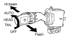
The light control switch cluster is located on the left side of the combination switch cluster. This light control switch cluster can control lights such as taillights, size lights, high-low beams, and turn signals. How to use the switch is described as in Figure 2.2
Picture
Function |
Figure 2.2. Car light control switch |
OFF | All the lights are off. |
| Parking lights, tail lights, license plate lights, overhead lights The dashboard is bright |
| Headlights and all lights All of the above are bright. |
Auto | Automatic headlight mode motion activated |


Maybe you are interested!
-
 Car body electrical practice - 11
 -
 Car Body Electrical Practice - 16
 -
 Car body electrical practice - 8
zt2i3t4l5ee
zt2a3gs
zt2a3ge
zc2o3n4t5e6n7ts
If the voltage is out of specification, replace the wire or connector.
If the voltage is within specification, install the front fog light relay and follow step 5.
Step 5 Check the front fog light switch
- Remove the D4 connector of the fog light switch
- Use a multimeter to measure the resistance of the front fog light switch.
Measurement location
Condition
Standard
D4-3 (BFG) -D4-4 (LFG)
Light switchFront Fog OFF
>10kΩ
D4-3 (BFG) -D4-4 (LFG)
Front fog light switchON
<1 Ω
- Standard resistor
D4 connector is located on the combination switch assembly.
If the resistance is out of specification, replace the combination switch (the fog light switch is located in the combination switch).
If the resistance is within specification, follow step 6.
Step 6 Check wiring and connectors (front fog light relay-light selector switch)
- Disconnect connector D4 of the combination switch assembly
- Use a voltmeter to measure the voltage value of jack D4 on the wire side.
Measurement location
Control modecontrol
Standard
D4-3 (BFG) - (-) AQ
TAIL
11 to 14 V
D4 connector for the wiring of the combination switch assembly
If the voltage does not meet the standard, replace the wire or connector.
If the voltage is within standard, there may have been an error in the previous measurements.
Step 7 Check the front fog lights
- Remove the front fog light electrical connector.
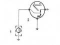
- Supply battery voltage to the fog lamp terminals
Jack 8, B9 of front fog lamp on the electrical side
blind first.
Power supply location
Terms and Conditions
Battery positive terminal - Terminal 2Battery negative terminal - Terminal 1
Fog lightsbefore morning
- If the light does not come on, replace the bulb.
If the light is on, re-plug the jack and continue to step 8.
Step 8 Check wiring and connectors (relay and front fog lights)
- Disconnect the B8 and B9 connectors of the front fog lights.
- Use a voltmeter to measure voltage at the following locations:
Measurement location
Switch location
Terms and Conditions
B8-2 - (-) AQ
Electric lock ON TAIL size switchFog switch ON
11 to 14 V
B9-2 - (-) AQ
Electric lock ONTAIL size switch Fog switch ON
11 to 14 V
B8 and B9 connectors on the front fog lamp wiring side
Voltage is not up to standard, repair or replace the jack. If up to standard, there may have been an error in the measurement process.
2.2.4. Procedure for removing, installing and adjusting fog lights 1. Procedure for removing
- Remove the front inner ear pads
Use a screwdriver to remove the 3 screws and remove the front part of the front inner ear liner
-Remove the fog light assembly
+ Disconnect the connector.
+ Use a screwdriver to remove 3 screws to remove the fog light cover
2. Installation sequence
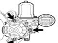
-Rotate the fog lamp bulb in the direction indicated by the arrow as shown in the figure and remove the fog lamp from the fog lamp assembly.
-Rotate the fog light bulb in the direction indicated by the arrow as shown in the figure and install the light into the fog light assembly.
- Use a screwdriver to install the fog light cover
-Install the electrical connector
Attention: Be careful not to damage the plastic thread on the lamp assembly.
- Install the front inner ear pads
Use a screwdriver to install the front inner bumper with 3 screws.
3. Prepare the vehicle to adjust the fog light convergence. Prepare the vehicle:
- Make sure there is no damage or deformation to the vehicle body around the fog lights.
- Add fuel to the fuel tank
- Add oil to standard level.
- Add engine coolant to standard level.
- Inflate the tire to standard pressure.
- Place spare tire, tools and jack in original design position
- Do not leave any load in the luggage compartment.
- Let a person weighing about 75 kg sit in the driver's seat.
4. Prepare to check the fog light convergence
a/ Prepare the vehicle status as follows:
- Place the car in a dark enough place to see the lines. The lines are the dividing line, below which the light from the fog lights can be seen but above which it cannot.
- Place the car perpendicular to the wall.
- Keep a distance of 7.62 m between the center of the fog lamp and the wall.
- Park the car on level ground.
- Press the car down a few times to stabilize the suspension.
Note: A distance of approximately 7.62 m is required between the vehicle (fog lamp center) and the wall to adjust the convergence correctly. If the distance of 7.62 m cannot be achieved, set the correct distance of 3 m to check and adjust the fog lamp convergence. (Since the target area varies with the distance, please follow the instructions as shown in the figure.)
b/ Prepare a piece of thick white paper about 2 m high and 4 m wide to use as a screen.
c/ Draw a vertical line through the center of the screen (line V).
d/ Set the screen as shown in the picture. Note:
- Keep the screen perpendicular to the ground.
- Align the V line on the screen with the center of the vehicle.
e/Draw the reference lines (H, V LH and V RH lines) on the screen as shown in the figure.HINT:
Mark the center of the fog lamp on the screen. If the center mark cannot be seen on the fog lamp, use the center of the fog lamp or the manufacturer's name mark on the fog lamp as the center mark.
H line (fog light height):
Draw a line across the screen so that it passes through the center mark. Line H should be at the same height as the center mark of the fog light bulb.
Line V LH, V RH (center mark position of left fog lamp LH and right fog lamp RH):
Draw two lines so that they intersect line H at the center marks.
5. Check the fog light convergence
a/ Cover the fog lamp or remove the connector of the other side fog lamp to prevent light from the unchecked fog lamp from affecting the fog lamp convergence test.
b/ Start the engine.
c/ Turn on the fog lights and make sure that the dividing line is outside the standard area as shown in the drawing.
6. Adjust the fog light convergence
Use a screwdriver to adjust the fog light to the standard area by turning the toe adjustment screw.
Note: If the screw is adjusted too far, loosen it and then tighten it again, so that the last rotation of the light adjustment screw is clockwise.
3. Self-study questions
1. Describe the operating principle of the lighting system with automatic headlight function
2. Describe the operating principle of the lighting system with the function of rotating headlights when turning
3. Draw diagram and connect lighting system on Hyundai Porter car
4. Draw diagram and connect lighting system on Honda Accord 1992
5. Draw the lighting circuit on a 1993 Toyota Lexus
LESSON 3 MAINTENANCE AND REPAIR OF SIGNAL SYSTEM
I. IMPLEMENTATION GOAL
After completing this lesson, students will be able to:
- Distinguish between types of signals on cars
- Correctly describe common symptoms and suspected areas causing damage.
- Connecting signal circuits ensures technical requirements
- Disassemble, install, check, maintain and repair the signal system to ensure technical requirements.
- Ensure safety in work and industrial hygiene
II. LESSON CONTENT
1. General description
The signal system equipped on cars aims to create signals to notify other vehicles participating in traffic about the vehicle's operating status such as: stopping, parking, braking, reversing, turning...
Signals are used either by light such as headlamps, brake lights, turn signals….. or by sound such as horns, reverse music….
Just like the lighting system. A signal system circuit usually consists of: battery, fuse, wire, relay, electrical load and control switch. Only some switches of the signal system are on the combination switch. The switches of other signals are usually located in different locations such as in the gearbox or brake pedal……
2. Maintenance and repair
2.1. Turn signals and hazard lights
The installation location of the turn signal is shown in Figure 3.1. The turn signal control switch is located in the combination switch under the steering wheel. Turning this switch to the right or left will make the turn signal turn right or left.
The hazard light switch is used when the vehicle has a problem while participating in traffic. When the hazard light switch is turned on, all the turn signals on the vehicle will light up at a certain frequency. The hazard light switch is usually placed separately from the turn signal switch (some old cars integrate the hazard and turn signal switches on the same combination switch cluster).
Figure 3.1 Turn signal switch Figure 3.2 Hazard switch
The part that generates the flashing frequency for the lights is called a turn signal relay. The turn signal relay usually has 3 terminals: B (positive power supply); E (negative power supply); L (providing the turn signal switch to distribute to the
lamp)
2.1.1. Circuit diagram
To generate the frequency for the turn signal, a turn signal relay is used in the turn signal circuit. The current from the turn signal relay will be sent to the turn signal switch assembly to distribute the current to the turn signal lights for the driver's purpose.
Figure 3.3. Schematic diagram of a turn signal circuit without a hazard switch
1. Battery; 2. Electric lock; 3. Turn signal relay; 4. Turn signal switch; 5. Turn signal lamp; 6. Turn signal lamp; 7. Hazard switch
Figure 3.4 Schematic diagram of turn signal circuit with hazard switch
1. Battery; 2. Combination switch cluster; 3. Turn signal;
4. Turn signal light; 5. Turn signal relay
Today's cars no longer use three-pin turn signal relays (B, L, E) but use eight-pin turn signal relays (figure 3.5) (pin number 8 is used for hazard lights).
For this type, the current supplying the turn signal lights is supplied directly from the turn signal relay to the lights.
div.maincontent .p { color: black; font-family:"Times New Roman", serif; font-style: normal; font-weight: normal; text-decoration: none; font-size: 14pt; margin:0pt; } div.maincontent p { color: black; font-family:"Times New Roman", serif; font-style: normal; font-weight: normal; text-decoration: none; font-size: 14pt; margin:0pt; } div.maincontent .s1 { color: black; font-family:"Times New Roman", serif; font-style: normal; font-weight: normal; text-decoration: none; font-size: 13pt; } div.maincontent .s2 { color: black; font-family:"Times New Roman", serif; font-style: italic; font-weight: normal; text-decoration: none; font-size: 14pt; } div.maincontent .s3 { color: black; font-family:"Times New Roman", serif; font-style: normal; font-weight: normal; text-decoration: none; font-size: 14pt; } div.maincontent .s4 { color: black; font-family:"Times New Roman", serif; font-style: normal; font-weight: normal; text-decoration: none; font-size: 13pt; } div.maincontent .s5 { color: black; font-family:"Times New Roman", serif; font-style: normal; font-weight: normal; text-decoration: none; font-size: 13pt; vertical-align: 1pt; } div.maincontent .s6 { color: black; font-family:"Times New Roman", serif; font-style: normal; font-weight: normal; text-decoration: none; font-size: 11pt; } div.maincontent .s7 { color: black; font-family:"Times New Roman", serif; font-style: normal; font-weight: normal; text-decoration: none; font-size: 14pt; vertical-align: -9pt; } div.maincontent .s8 { color: black; font-family:"Times New Roman", serif; font-style: normal; font-weight: normal; text-decoration: none; font-size: 11pt; } div.maincontent .s9 { color: #008000; font-family:"Times New Roman", serif; font-style: normal; font-weight: normal; text-decoration: none; font-size: 14pt; } div.maincontent .s10 { color: black; font-family:"Times New Roman", serif; font-style: italic; font-weight: normal; te
Car body electrical practice - 8
zt2i3t4l5ee
zt2a3gs
zt2a3ge
zc2o3n4t5e6n7ts
If the voltage is out of specification, replace the wire or connector.
If the voltage is within specification, install the front fog light relay and follow step 5.
Step 5 Check the front fog light switch
- Remove the D4 connector of the fog light switch
- Use a multimeter to measure the resistance of the front fog light switch.
Measurement location
Condition
Standard
D4-3 (BFG) -D4-4 (LFG)
Light switchFront Fog OFF
>10kΩ
D4-3 (BFG) -D4-4 (LFG)
Front fog light switchON
<1 Ω
- Standard resistor
D4 connector is located on the combination switch assembly.
If the resistance is out of specification, replace the combination switch (the fog light switch is located in the combination switch).
If the resistance is within specification, follow step 6.
Step 6 Check wiring and connectors (front fog light relay-light selector switch)
- Disconnect connector D4 of the combination switch assembly
- Use a voltmeter to measure the voltage value of jack D4 on the wire side.
Measurement location
Control modecontrol
Standard
D4-3 (BFG) - (-) AQ
TAIL
11 to 14 V
D4 connector for the wiring of the combination switch assembly
If the voltage does not meet the standard, replace the wire or connector.
If the voltage is within standard, there may have been an error in the previous measurements.
Step 7 Check the front fog lights
- Remove the front fog light electrical connector.
- Supply battery voltage to the fog lamp terminals
Jack 8, B9 of front fog lamp on the electrical side
blind first.
Power supply location
Terms and Conditions
Battery positive terminal - Terminal 2Battery negative terminal - Terminal 1
Fog lightsbefore morning
- If the light does not come on, replace the bulb.
If the light is on, re-plug the jack and continue to step 8.
Step 8 Check wiring and connectors (relay and front fog lights)
- Disconnect the B8 and B9 connectors of the front fog lights.
- Use a voltmeter to measure voltage at the following locations:
Measurement location
Switch location
Terms and Conditions
B8-2 - (-) AQ
Electric lock ON TAIL size switchFog switch ON
11 to 14 V
B9-2 - (-) AQ
Electric lock ONTAIL size switch Fog switch ON
11 to 14 V
B8 and B9 connectors on the front fog lamp wiring side
Voltage is not up to standard, repair or replace the jack. If up to standard, there may have been an error in the measurement process.
2.2.4. Procedure for removing, installing and adjusting fog lights 1. Procedure for removing
- Remove the front inner ear pads
Use a screwdriver to remove the 3 screws and remove the front part of the front inner ear liner
-Remove the fog light assembly
+ Disconnect the connector.
+ Use a screwdriver to remove 3 screws to remove the fog light cover
2. Installation sequence
-Rotate the fog lamp bulb in the direction indicated by the arrow as shown in the figure and remove the fog lamp from the fog lamp assembly.
-Rotate the fog light bulb in the direction indicated by the arrow as shown in the figure and install the light into the fog light assembly.
- Use a screwdriver to install the fog light cover
-Install the electrical connector
Attention: Be careful not to damage the plastic thread on the lamp assembly.
- Install the front inner ear pads
Use a screwdriver to install the front inner bumper with 3 screws.
3. Prepare the vehicle to adjust the fog light convergence. Prepare the vehicle:
- Make sure there is no damage or deformation to the vehicle body around the fog lights.
- Add fuel to the fuel tank
- Add oil to standard level.
- Add engine coolant to standard level.
- Inflate the tire to standard pressure.
- Place spare tire, tools and jack in original design position
- Do not leave any load in the luggage compartment.
- Let a person weighing about 75 kg sit in the driver's seat.
4. Prepare to check the fog light convergence
a/ Prepare the vehicle status as follows:
- Place the car in a dark enough place to see the lines. The lines are the dividing line, below which the light from the fog lights can be seen but above which it cannot.
- Place the car perpendicular to the wall.
- Keep a distance of 7.62 m between the center of the fog lamp and the wall.
- Park the car on level ground.
- Press the car down a few times to stabilize the suspension.
Note: A distance of approximately 7.62 m is required between the vehicle (fog lamp center) and the wall to adjust the convergence correctly. If the distance of 7.62 m cannot be achieved, set the correct distance of 3 m to check and adjust the fog lamp convergence. (Since the target area varies with the distance, please follow the instructions as shown in the figure.)
b/ Prepare a piece of thick white paper about 2 m high and 4 m wide to use as a screen.
c/ Draw a vertical line through the center of the screen (line V).
d/ Set the screen as shown in the picture. Note:
- Keep the screen perpendicular to the ground.
- Align the V line on the screen with the center of the vehicle.
e/Draw the reference lines (H, V LH and V RH lines) on the screen as shown in the figure.HINT:
Mark the center of the fog lamp on the screen. If the center mark cannot be seen on the fog lamp, use the center of the fog lamp or the manufacturer's name mark on the fog lamp as the center mark.
H line (fog light height):
Draw a line across the screen so that it passes through the center mark. Line H should be at the same height as the center mark of the fog light bulb.
Line V LH, V RH (center mark position of left fog lamp LH and right fog lamp RH):
Draw two lines so that they intersect line H at the center marks.
5. Check the fog light convergence
a/ Cover the fog lamp or remove the connector of the other side fog lamp to prevent light from the unchecked fog lamp from affecting the fog lamp convergence test.
b/ Start the engine.
c/ Turn on the fog lights and make sure that the dividing line is outside the standard area as shown in the drawing.
6. Adjust the fog light convergence
Use a screwdriver to adjust the fog light to the standard area by turning the toe adjustment screw.
Note: If the screw is adjusted too far, loosen it and then tighten it again, so that the last rotation of the light adjustment screw is clockwise.
3. Self-study questions
1. Describe the operating principle of the lighting system with automatic headlight function
2. Describe the operating principle of the lighting system with the function of rotating headlights when turning
3. Draw diagram and connect lighting system on Hyundai Porter car
4. Draw diagram and connect lighting system on Honda Accord 1992
5. Draw the lighting circuit on a 1993 Toyota Lexus
LESSON 3 MAINTENANCE AND REPAIR OF SIGNAL SYSTEM
I. IMPLEMENTATION GOAL
After completing this lesson, students will be able to:
- Distinguish between types of signals on cars
- Correctly describe common symptoms and suspected areas causing damage.
- Connecting signal circuits ensures technical requirements
- Disassemble, install, check, maintain and repair the signal system to ensure technical requirements.
- Ensure safety in work and industrial hygiene
II. LESSON CONTENT
1. General description
The signal system equipped on cars aims to create signals to notify other vehicles participating in traffic about the vehicle's operating status such as: stopping, parking, braking, reversing, turning...
Signals are used either by light such as headlamps, brake lights, turn signals….. or by sound such as horns, reverse music….
Just like the lighting system. A signal system circuit usually consists of: battery, fuse, wire, relay, electrical load and control switch. Only some switches of the signal system are on the combination switch. The switches of other signals are usually located in different locations such as in the gearbox or brake pedal……
2. Maintenance and repair
2.1. Turn signals and hazard lights
The installation location of the turn signal is shown in Figure 3.1. The turn signal control switch is located in the combination switch under the steering wheel. Turning this switch to the right or left will make the turn signal turn right or left.
The hazard light switch is used when the vehicle has a problem while participating in traffic. When the hazard light switch is turned on, all the turn signals on the vehicle will light up at a certain frequency. The hazard light switch is usually placed separately from the turn signal switch (some old cars integrate the hazard and turn signal switches on the same combination switch cluster).
Figure 3.1 Turn signal switch Figure 3.2 Hazard switch
The part that generates the flashing frequency for the lights is called a turn signal relay. The turn signal relay usually has 3 terminals: B (positive power supply); E (negative power supply); L (providing the turn signal switch to distribute to the
lamp)
2.1.1. Circuit diagram
To generate the frequency for the turn signal, a turn signal relay is used in the turn signal circuit. The current from the turn signal relay will be sent to the turn signal switch assembly to distribute the current to the turn signal lights for the driver's purpose.
Figure 3.3. Schematic diagram of a turn signal circuit without a hazard switch
1. Battery; 2. Electric lock; 3. Turn signal relay; 4. Turn signal switch; 5. Turn signal lamp; 6. Turn signal lamp; 7. Hazard switch
Figure 3.4 Schematic diagram of turn signal circuit with hazard switch
1. Battery; 2. Combination switch cluster; 3. Turn signal;
4. Turn signal light; 5. Turn signal relay
Today's cars no longer use three-pin turn signal relays (B, L, E) but use eight-pin turn signal relays (figure 3.5) (pin number 8 is used for hazard lights).
For this type, the current supplying the turn signal lights is supplied directly from the turn signal relay to the lights.
div.maincontent .p { color: black; font-family:"Times New Roman", serif; font-style: normal; font-weight: normal; text-decoration: none; font-size: 14pt; margin:0pt; } div.maincontent p { color: black; font-family:"Times New Roman", serif; font-style: normal; font-weight: normal; text-decoration: none; font-size: 14pt; margin:0pt; } div.maincontent .s1 { color: black; font-family:"Times New Roman", serif; font-style: normal; font-weight: normal; text-decoration: none; font-size: 13pt; } div.maincontent .s2 { color: black; font-family:"Times New Roman", serif; font-style: italic; font-weight: normal; text-decoration: none; font-size: 14pt; } div.maincontent .s3 { color: black; font-family:"Times New Roman", serif; font-style: normal; font-weight: normal; text-decoration: none; font-size: 14pt; } div.maincontent .s4 { color: black; font-family:"Times New Roman", serif; font-style: normal; font-weight: normal; text-decoration: none; font-size: 13pt; } div.maincontent .s5 { color: black; font-family:"Times New Roman", serif; font-style: normal; font-weight: normal; text-decoration: none; font-size: 13pt; vertical-align: 1pt; } div.maincontent .s6 { color: black; font-family:"Times New Roman", serif; font-style: normal; font-weight: normal; text-decoration: none; font-size: 11pt; } div.maincontent .s7 { color: black; font-family:"Times New Roman", serif; font-style: normal; font-weight: normal; text-decoration: none; font-size: 14pt; vertical-align: -9pt; } div.maincontent .s8 { color: black; font-family:"Times New Roman", serif; font-style: normal; font-weight: normal; text-decoration: none; font-size: 11pt; } div.maincontent .s9 { color: #008000; font-family:"Times New Roman", serif; font-style: normal; font-weight: normal; text-decoration: none; font-size: 14pt; } div.maincontent .s10 { color: black; font-family:"Times New Roman", serif; font-style: italic; font-weight: normal; te -
 Measurement and Remote Control – Electrical Engineering Industry - 8
 -
 Enforcement of fines from practice in District 2, Ho Chi Minh City - 8
On vehicles manufactured in recent years, the headlights can turn on automatically when moving in low light environments, the light intensity of the headlights can be changed, and the light beam of the headlights can also be changed automatically when the vehicle turns. If the lighting system is controlled by the lighting control ECU, the operation and control are described as follows
- When any of the following conditions are met, the ceiling light will gradually brighten.
+ There is any door open.
+ Any door is unlocked when the ignition is OFF and all doors are closed.
+ The electric lock is turned from ON to OFF when all doors are closed.
- When one of the following conditions is met, the ceiling light will turn off.
+ The electric lock is turned from OFF to ON when all doors are closed.
+ All doors are locked when the power switch is OFF.
- Lights up for about 15 seconds, and then fades out when all doors are closed with the power off.
- When all of the following conditions are met, the lamp control ECU will turn off all lamps.
+ The key is not in the ignition lock.
+ No change in door lock status for 20 minutes.
- When any of the following conditions are met, the battery save counter will be cleared.
+The key is in the ignition lock.
+ Any door open.
34
2. Maintenance and repair
2.1. Dimensions of lights and high-beam and low-beam lights
The front lighting system is the most basic and important lighting system on the vehicle to ensure working conditions for the driver, especially at night. Front lighting is always improved to increase vehicle safety when traveling on the road.
Headlights today are manufactured based on two levels of light: high beam and low beam. The headlight's ability can be from 180 - 250m and the near beam from 50 - 75m . Headlights are one of the devices that consume a lot of power on cars, in high beam mode it is 45 - 70W , in near beam mode it is 35 - 40W .
Headlights play an extremely important role when a car is moving, so headlights are always improved to improve lighting and save energy... Headlights often use the following types of bulbs:
- Incandescent bulbs, halogen bulbs
- Xenon lights: Low beams use Xenon lights, high beams still use Halogen bulbs
- Xenon Bi-xenon Headlights: Both high and low beams use Xenon. The above two types of lights are also known as HID lights.
- Led lights: This type of light has high light intensity but low power and is used in most modern cars today.
The dimmer and high beam are always connected to the same circuit, the dimmer is installed behind the white bulb, the red lens depending on the type. The high beam includes the high beam and the low beam. There are many methods of connecting the circuit but all must satisfy the following requirements:
- Do not turn on the ignition, turn on the light selector switch at the Tail position, only the size light is on.
High beam and low beam do not light up
- Do not turn on the ignition, when turning the light selector switch to the Head position, the size light will still be on and the high beam or low beam will be on. At this time, to change the phase or low beam, select the Phase or Low position on the Phase-Low beam switch.
- The ignition is not turned on, the light selector switch is in the OFF position, the size light, high beam and low beam do not light up, turn on the flashing switch, the headlights light up
When wiring a circuit diagram, it is very important to find out the meaning of the terminals in the combination switch assembly (if there is no EWD). The search sequence is performed in the following order. The instrument used is an ohmmeter based on the principle of exclusion.
- Control for all switches to OFF mode
- Find the left and right turn signal control poles
- Find the phase flash control pole
- Find the size lamp control terminal at the lamp selector switch
- Find the high-low beam control terminal on the light selector switch
- Find the control pole in phase or core mode
2.1.1. Circuit diagram
a, Type without relay
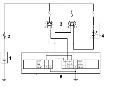
Figure 2.4 High-beam-low-beam system without control relay
1. Battery; 2. Fuse; 3. Headlight;
4. Headlight; 5. Combination switch cluster
b.Type using positive standby relay
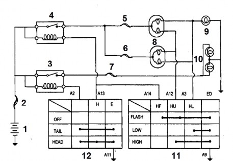
Figure 2.5 Diagram of the standby high-beam-low beam control switch
1. Battery; 2. Main fuse; 3. Dimension lamp relay;
4. High beam-low beam relay; 5. High beam fuse; 6. Low beam fuse;
7. Dimension lamp fuse; 8. Low beam headlight cluster; 9. High beam indicator light; 10. Dimension lamp; 11,12. Combination switch cluster
c. Type using standby negative relay
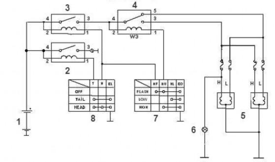
Figure 2.6 Circuit diagram of standby negative light control
1. Battery; 2. Vehicle size light relay; 3. Headlight relay;
4. High-beam-low-beam relay; 5. Low-beam headlight assembly; 6. High-beam indicator light;
7. High-beam/low-beam selector switch; 8. High-beam/low-beam selector switch
d, Automatic headlight circuit
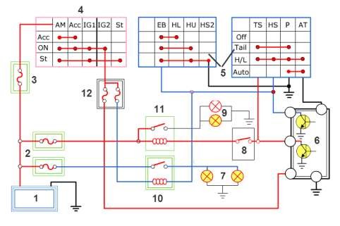
Figure 2.7 Automatic headlight circuit diagram
1. Battery; 2, 3,12. Fuse; 4. Electric lock; 5. Combination switch;
6. Auto headlight sensor; 7. Headlight; 8. ETACSCM;
9. Dimension lamp; 10. Headlight relay; 11. Dimension lamp relay
In this circuit, sensor number 6 detects the light conditions in the area where the vehicle is moving. For example, when entering a dark tunnel, the sensor will automatically connect negative to relay number 11 so that the headlights are turned on.
e, Automatic Headlight Switching Circuit (AFS)
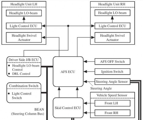
Figure 2.8 Block diagram of lighting system with headlight rotation function
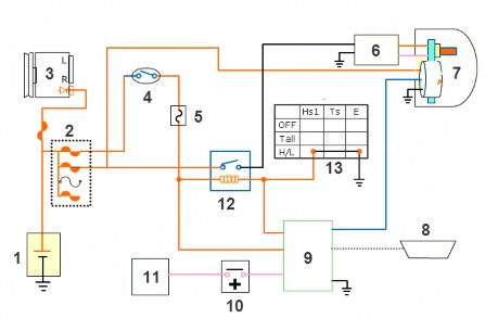
Figure 2.9 Schematic diagram of the AHLS automatic headlight control system circuit
1. Battery; 2, 5. Fuse; 3. Alternator; 4. Ignition switch; 6. Turbocharger; 7. HID lamp;
8. Diagnostic connector; 9. AHLS CM; 10. Wheel speed sensor;
11. ECU; 12. Headlight relay; 13. Light control switch
When the vehicle moves into a turn, there will be dark areas where the light cannot shine, this system has the function of controlling the headlight beam into the dark area to ensure traffic safety when turning. This light will turn on when receiving signals: turn signal, vehicle speed, steering angle
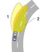
Figure 2.10 Light area of a vehicle equipped with a headlight rotation function
1. Conventional lighting system
2. Lighting system equipped with headlight rotation function
In addition to the headlight rotation function, the system is also equipped with a headlight direction control function when the truck body is unevenly distributed on the vehicle, such as when the vehicle is carrying more people or luggage or entering roads with large bumps.
Now the height sensor works and will adjust the light direction.
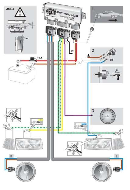
Figure 2.11. Schematic diagram of the smart headlight system
1. Headlight; 2. Control switch; 3. AFS indicator light
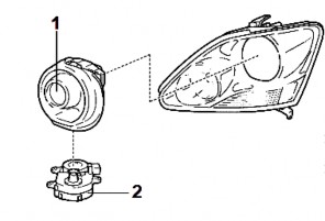
Figure 2.12. Structure of a smart headlight cluster
1. Headlight; 2. Headlight rotating stepper motor (headlight actuator)
2.1.2. Symptoms and suspected areas
The faults in the lighting system of the vehicle may be similar, but the suspected problem area is different because it depends on the structure of the circuit and its circuit diagram. If a circuit has many components, the suspected problem area will be larger. Therefore, this symptom chart is only for Toyota vehicles with the connection diagram in Figure 2.10. For each lighting system, a circuit diagram is required to localize the fault area of the system.
Symptom
Suspicious area | |
All headlights are not on. | - Light control switch - Power cord or connector |
Only one headlight (low beam) is on. | - Light bulb - Fuse - Power cord or connector |
The low beam headlights do not illuminate. | - Light control switch - Power cord or connector |
Only one headlight (high beam) is on. | - Light bulb - Fuse - Power cord or connector |
The headlights (high beam) do not light up. | - Light control switch - Power cord or connector |
Headlights do not flash. (The headlights and normal Hi-beam lights) | - Light control switch - Power cord or connector |
Taillights not on (Headlights normal) | - TAIL fuse - Light control switch - Power cord or connector |
The front size lights are not bright. | - Light bulb - Power cord or connector |
The tail lights are not on. | - Light bulb |