Lesson 7.2 : Lathe eccentric shaft on 3-jaw, 4-jaw chuck (06 periods)
A. Teaching facilities and equipment
1. Means
Lesson plans, outlines, chalk, projector, drawings, ...
2. Equipment
T
T
Name and specifications of the device, tools; raw materials, consumables | Single taste | SL | Note | Additional | |
1 | Equipment, tools (for 01 student) | ||||
- Universal lathe (3-jaw chuck, 4-pin, wrench) | Female | 01 | |||
- Fixed or rotating center point | Female | 01 | |||
- Cutting tool grinder (shared) | Female | 01 | |||
- Measuring tools: 1/50 caliper, ruler | Set | 01 | |||
- Cutting tool: external turning tool (curved tip, shoulder cutter: T15K6 or P18); center drill | Set | 01 | |||
2 | Raw materials, consumables (for 01 student) | ||||
- Steel CT45 ( 40x100)mm | Female | 01 | |||
- Engine oil | Liter | ||||
- Cleaning cloth | Kg | 0.2 | Cancel | ||
3 | Other |
Maybe you are interested!
-

 Positioning the My Le tourist area brand in Ho Chi Minh City market - 1
 -
 Brand Positioning and Development Associated with Corporate Culture
 -
 Combined Positioning Using One Plane And Two Holes Perpendicular To The Plane
 -
 Target Market Selection and Market Positioning
 -
 Vinamilk Brand Positioning Activities in the International Market
B. Implement the lesson
1. Lesson objectives
After completing this lesson, students will be able to:
About knowledge
- Know how to calculate and determine eccentricity on eccentric shaft details.
- Know the method of mounting the workpiece on a 3-jaw or 4-jaw chuck to turn eccentric shaft details.
About skills
- The workpiece can be placed on the cutting tray to turn the eccentric shaft.
- Eccentric shaft details can be machined to ensure technical requirements.
About attitude
Serious and proactive in learning and practicing industrial production style. Ensure labor safety and environmental hygiene.
2. Lesson content
2.1. Characteristics of eccentric shaft
- Eccentric shafts are shafts that have at least 2 or more shaft collars.
- The center line and the generator line of the shaft necks are always parallel to each other.
- The center lines of the shafts are not concentric with each other, but are offset by a distance, that distance is called the eccentricity of the shafts, denoted by (e).
- The eccentricity (e) of the shaft collars may or may not be within the end face of the workpiece (less than or greater than the workpiece radius).
Machining eccentric shafts with more collars becomes more complicated, especially when the eccentricity (e) between the collars is larger than the radius of the workpiece.
When using a 3-jaw or 4-jaw chuck, it is often used to turn eccentric shafts with 2 shaft collars, each shaft collar length is short.
2.2. Position and clamp the workpiece on the chuck for eccentric shaft turning
2.2.1. On 3-jaw chuck
- The workpiece must be face-down and machined to the outer diameter of a shaft neck.
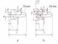
- When mounting on a 3-jaw chuck, use a pad (the thickness of the pad is calculated similarly to when turning an eccentric bush on a 3-jaw chuck), pad one jaw of the chuck, similar to when turning an eccentric bush (Figure 7.5). Note to check that the shaft's generating line is parallel to the center of the machine before clamping the workpiece.
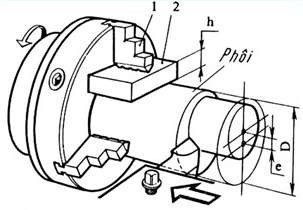
Figure 7.5 Eccentric shaft turning on three-jaw chuck
2.2.2. On 4-jaw chuck
- The blank has been face-masked, lathe to the size of a shaft collar and mark the eccentric distance and diameter of the eccentric shaft collar to be lathe (similar to when turning an eccentric bushing on a 4-jaw chuck), as shown in Figure 7.6
- Perform checking and mounting of workpieces:
Figure 7.6 Checking the workpiece on the four-jaw chuck
Step 1: Mount the workpiece on the 4-jaw chuck, then trace the outer diameter (Note: the marking line passing through the center of the outer cylindrical face and the inner cylindrical face on the end face of the workpiece must be brought to the middle position of a chuck jaw, as shown in Figure 7.6).
Step 2: Adjust the 2 jaws A, B so that the center of the inner cylinder coincides with the center of the machine, clamp the 2 jaws C, D tightly, then clamp the 2 jaws A, B tightly (figure 7.7)
Note to check the shaft's generating line parallel to the machine center before clamping the workpiece on the 4-jaw chuck.
A
A
B
CDCD
B
Figure 7.7 Checking the fixture on the four-jaw chuck
2.4. Tool selection: Selecting a tool for turning an eccentric shaft is similar to that for turning an outer cylindrical surface.
2.5. Select cutting mode: When machining eccentrically, the cutting mode is similar to cylindrical turning. However, initially, when machining, the cutting process often vibrates, so the cutting mode is often reduced to reduce the vibration process.
2.5. Implementation sequence
2.5.1. Preparation
- Prepare blank: check size and material type;
- Prepare the lathe: check the machine's operation, ensure safety;
- Prepare equipment according to the machine: 3-jaw and 4-jaw chuck, dial gauge, radio
line;
- Prepare cutting tools: external turning tool;
- Prepare measuring tools: calipers, micrometers, markers, dots;
- Prepare tools for industrial cleaning.
2.5.2. Workpiece holder and tool holder
- Position and clamp the workpiece on the 3-jaw or 4-jaw cutting chuck.
- The tool holder is similar to that for external turning.
2.5.3. Adjusting and operating the lathe
- Adjust the levers on the main shaft speed box and the tool speed box to the determined speed for turning.
- Machine operation: Check the safety of the machine before running, the knife has not been used for cutting.
2.5.4. Sequence of processing steps
Step 1: Rough turning, calculate the remaining amount for fine turning. Step 2: Check
Step 3: Finish the cylindrical surface.
Step 4: Final Inspection: Perform an overall inspection of the product before removing it from the machine.
2.6. Types of failures, causes and prevention
TT
Failure mode | Reason | How to fix | |
1 | Eccentricity (e) is not correct | - Inaccurate marking, - Check and fix the workpiece incorrectly. | - Mark and check accurately, check again before processing. Use a dial indicator to check the displacement of the jaws. |
2 | The center lines of the shafts are not parallel to each other. | - Workpiece holder is not parallel to machine center. - Embryo is translocated in machining process | - Must combine circular scanning with concentric scanning. - Clamp the workpiece tightly enough, reduce the mode cut |
- Cutting mode is not reasonable, | - Select the appropriate cutting mode. | ||
- Geometric parameters of | - Choose the right knife angle. | ||
3 | Surface roughness not achieved | unreasonable knife, broken knife blunt | - Firmly hold the knife and workpiece, reducing |
- Vibration during operation | cutting mode | ||
cutting process |
3. Organize skill training
3.1. Practice requirements
a. Drawing
b. Requirement: Turning eccentric shaft details on three-jaw or four-jaw chuck according to drawing requirements (quantity 01)
3.2.2. Sequence of processing steps
TT
Sequence | Diagram | Technical requirements | |
1 | Step 1: Tool holder and workpiece | - The knife tip must be level with the center of the part. - The workpiece is clamped tightly enough on the 4-jaw chuck, the size is correct as diagram | |
2 | Step 2: Front face | S1 n = 600-900 rpm; t = 0.5mm; S= hand | Head clearance L=48.5 |
3 | Step 3: Rough turning of cylinder 32.5 | S n = 400-600 rpm; t = 1.5mm; S= 0.2mm/vg | Check the amount left for the finishing step. |
Step 4: Convenient 32 and chamfered | S2 S1 n = 600-900 rpm; t = 0.5mm; S = 0.05mm/vg | Accurate measurement of dimensions | |
5 | Step 5: | Fix the workpiece so that | |
Naked | knife can be turned | ||
head and lathe | cylindrical surface, need | ||
pillar 40 |
| ensure roughness | |
S1 | surface 40 | ||
S2 | |||
n = 600-900 rpm; t = 0.5mm; S = 0.05mm/vg | |||
6 | Step 6: Check Eccentric fixture e = 2 on four-jaw chuck | n = hand | |
7 | Step 7: Eccentric rough turning | S2 S1 n = 300-600 rpm; t = 0.5mm; S = 0.1mm/vg | Convenient to use size 32 -0.1 |
4
Step 8: Eccentric finishing | S2 S1 n = 600-900 rpm; t = 0.2mm; S = 0.05mm/vg | ||
9 | Step 8: Test | Check the diameter and length of the cylinder face according to drawing requirements |
8
4. Self-study guide
a. Advantages and disadvantages of four-chuck chuck when machining eccentrically.
b. Advantages and disadvantages of eccentric turning method on three-shaft chuck using pad alignment.
Lesson 7.3 : Lathe eccentric shaft when mounted on 2 center points (06 periods)
A. Teaching facilities and equipment
1. Means
Lesson plans, outlines, chalk, projector, drawings, ...
2. Equipment
T
T
Name and specifications of the device, tools; raw materials, consumables | Single taste | SL | Note | Additional | |
1 | Equipment, tools (for 01 student) | ||||
- Universal lathe (3-jaw chuck, 4-pin, wrench) | Female | 01 | |||
- Fixed or rotating center point | Female | 01 | |||
- Cutting tool grinder (shared) | Female | 01 | |||
- Measuring tools: 1/50 caliper, ruler | Set | 01 | |||
- Cutting tool: external turning tool (curved tip, shoulder cutter: T15K6 or P18); center drill | Set | 01 | |||
2 | Raw materials, consumables (for 01 student) | ||||
- Steel CT45 ( 40x100)mm | Female | 01 | |||
- Engine oil | Liter | ||||
- Cleaning cloth | Kg | 0.2 | Cancel | ||
3 | Other |
B. Implement the lesson
1. Lesson objectives
After completing this lesson, students will be able to:
About knowledge
- Know how to mount the part on a 3-jaw or 4-jaw chuck for easy offset
heart.
About skills
- Eccentric shaft details can be machined to ensure technical requirements.
About attitude
- Serious and proactive in learning and practicing production style
industry. Ensure labor safety and environmental hygiene.