Relative motion between the working surface of the center drill and the center hole causes the center hole to wear quickly, affecting accuracy.
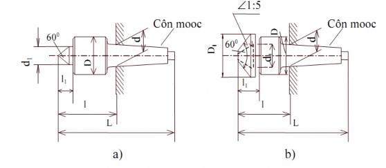
Figure 2-14: Rotating center point
Maybe you are interested!
-
 Theoretical mechanics of Metal cutting profession - Vocational college Part 2 - General Department of Vocational Training - 9
 -
 Autocad Textbook for Metal Cutting Profession - College of Technology - Dong Thap Vocational College - 12
 -
 Research on the fabrication and gas sensitivity of heterostructures between SnO2 nanowires and some semiconducting metal oxides - 16
 -
 Research on the treatment of seafood wastewater by electrocoagulation method combined with USBF - 19 tank
 -
 Study on fabrication and gas sensitivity of heterostructure between SnO2 nanowires and some semiconducting metal oxides - 17
4. Combined positioning
In practice, people often use multiple surfaces as positioning standards at the same time. When using this positioning method, it is important to note: do not use super positioning; must take into account manufacturing errors and assembly gaps of the positioning details.
4.1. Combined positioning with a plane and two holes perpendicular to the plane
This method is widely used to process box-shaped parts, machine bodies, forks, etc. This is a positioning method using a unified standard, easily ensuring the accuracy of the relative position. In cases where there is no hole surface on the part to use as a unified standard, the precisely machined bolt hole can be used as a positioning standard.
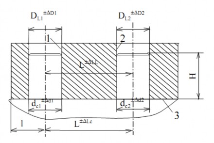
Figure 2-15: Combined positioning using a plane and two locating holes
For example: Figure 2-15; holes 1, 2 and plane 3 are the positioning standards. Due to the size distance between the two hole centers and the two pin centers changing within the tolerance range, due to the size tolerance of the diameters of the two pins and the two holes, and due to the assembly clearance between the pin and the holes, it may result in the two holes not being able to fit into the two pins.
To solve the above problem we can use the following two methods:
- First method: Reduce the diameter of a pin to increase the gap between the hole and the pin in the direction connecting the two hole centers in order to compensate for the tolerance of the distance between the two hole centers and the two pin centers. For ease of analysis, assume that the first hole is installed in the first pin, the pin center and the hole center coincide, we reduce the second pin line. It is necessary to satisfy the requirement that the largest size of the second pin can be installed in the second hole under the condition that the diameter of the two holes is the smallest, the diameter of the two pins is the largest, and the distance between the two hole centers is the largest, the distance between the two pin centers is the smallest (or vice versa, the distance between the two holes is the smallest, the distance between the two pin centers is the largest).
This method can solve the problem of mounting the part on two pins, but there is a large rotation angle error. Therefore, it is only applicable when the machining accuracy requirement is low.
- Method 2: Make the second pin a bevel pin (filling pin) to reduce the rotation angle error, while still ensuring convenience for the part to be mounted on the two pins. This is a commonly used method.
4.2. Locating with a plane and a chamfered pin with the centerline parallel to the plane
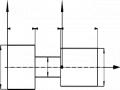
This case can be considered as a special case when locating with a plane and two holes where the first hole and the first pin turn into a plane.
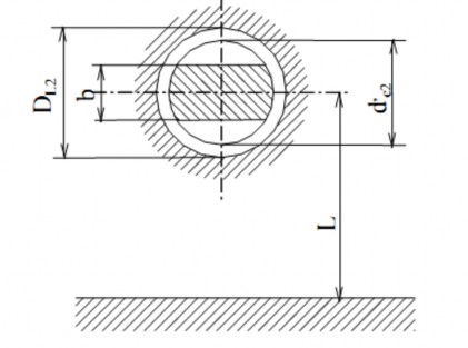
Figure 2-16: Locating with a plane and a D-shaped pin
4.3. Positioning by special surface
In addition to the surfaces commonly used as positioning reference surfaces mentioned above, people sometimes use some special surfaces to position details.
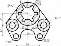
4.3.1. Positioning by gear rolling surface
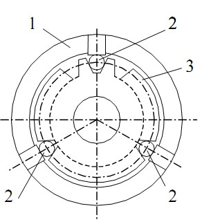
Figure 2-17
Figure 2-17 is an example of using the gear rolling surface as a positioning reference to grind the inner surface (hole). The positioning part is 3 high-precision rollers 2 that contact the tooth surface at 3 equally spaced positions to perform centering of part 3, thus ensuring the concentricity between the hole and the gear rolling surface after grinding, and also ensuring the even grinding allowance of the hole.
4.3.2. Positioning by guide surface.
People often use a 55o angle swallowtail guide surface or a V-shaped block to locate the part. There are two cases:
- Locate using a locating detail with a similar shape, figure 2-18.
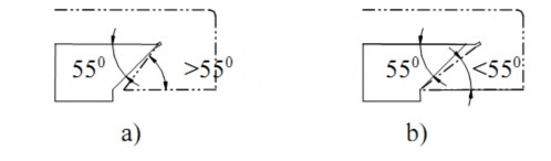
Figure 2-18
Due to the angular error of the guide surface, when it is larger (Figure 2-18a) or smaller (Figure 2-18b), it will cause the contact position between the positioning detail and the guide surface to change, which means increasing the positioning error.
Use one long pin or two short pins for positioning. Figure 2-19, for example, uses short pin 2 for positioning. The position between the guide surface and the two fixed pins, thus reducing the positioning error, overcoming the shortcomings of the above case.
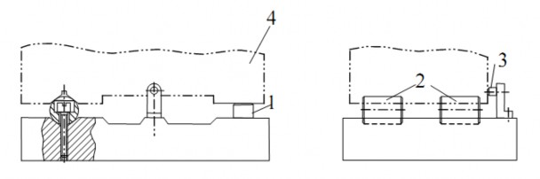
Figure 2-19:1-support plate; 2-short pillar; 3-support pin; 4- detail
5. Positioning error
5.1. Positioning error when positioning by plane
Positioning error occurs due to manufacturing error of the positioning surface of the workpiece and the positioning surface of the fixture's positioning part.
5.2. Positioning error when the part is positioned by the outer surface on the V-block
As presented above, the center of the outer surface of the part is the positioning standard, so calculating the positioning error is to calculate the largest variation of the center of the outer surface in a series of machined parts.
The calculation diagram is as shown in Figure 2-20. When the detail has the largest diameter of D +∆D , the center of the outer surface is O; when the detail has the smallest diameter of D -∆D , the detail moves down until it contacts block V. At this time, point A on the circumference will move to A 1 , correspondingly, the center O moves to O 1 , OO 1 is the amount of position change of the positioning standard caused by the position error of the positioning surface.
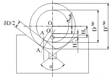
Figure 2-20
Positioning error depends on the tolerance of the external positioning reference surface size of the part and the angle value α of block V.
5.3. Positioning error when positioning by inner surface
5.3.1. Calculating positioning error when using mounting pins
The fixture pin and the hole are in any position. When the fixture pin is placed vertically, the positioning standard and the fixture pin can be in any position (Figure 2-21a). In the case where the hole has the largest diameter and the fixture pin has the smallest diameter, the positioning standard error is the displacement of the geometric center of the hole O 1ct O 2ct :

In there:
D. nominal diameter of the locating hole face.
± D. deviation of diameter of locating hole face. d. nominal diameter of fixture pin.
± d. tolerance of the diameter of the fixture pin. δD. tolerance of the hole diameter.
δd. tolerance on the diameter of the fixture pin.
∆- minimum clearance between the fixture pin and the locating hole face.
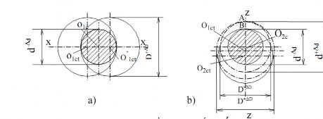
Figure 2-21: Standard error calculation diagram
a- Pin in any position; b- Pin in horizontal position
The fixture is in a horizontal position (Figure 2-221b). In this case, any part mounted on the fixture tends to fall downwards.
There are two cases: The fixture pin has the largest size d and the locating hole d +∆d has the smallest size D -∆D , at this time the contact position between the fixture pin and the locating hole at point A is the highest, the center of the part is o 1ct . The fixture pin has the smallest size d -∆d and the locating hole has the largest size D -∆D , at this time the contact position between the fixture pin and the locating hole at point B is the lowest, the center of the part is o 2ct.
In both cases, the center of the part moves in the zz direction, or in other words, the positioning error in the zz direction is O 1ct O 2ct . We have:
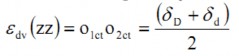
Meanwhile, the positioning error in the xx direction is zero.
Note: When calculating the standard positioning error, it is necessary to specify the size to be calculated, and at the same time consider the eccentricity e between the outer surface of the part and the inner surface which is the standard positioning surface, as well as the error of the outer diameter.
5.3.2. Calculating standard error when mounting parts on a tapered mandrel
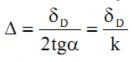
Although there is a manufacturing error of the hole face Figure 2-22: Error in locating the part, but with this method of positioning by the conical mandrel, the positioning reference face of the part is always in contact with the conical pin and thus eliminates the gap, or the diametric positioning standard error is zero. But due to the manufacturing error, the part of the whole series moves in the direction of the part axis (Figure 2-22). The amount of displacement is ∆, determined by the formula:
In which: k. taper of mandrel; α. taper angle of mandrel
CHAPTER 2 REVIEW QUESTIONS
Question 1. Describe the principle of 6-point positioning?
Question 2. What is the definition and requirements for a positioning map?
Question 3. Please state the details of locating the plane, outer cylinder, and inner cylinder?