For external matching (ψ = 1.5), we have:
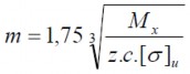
To fit in:
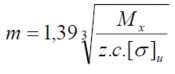
Allowable bending stress:

In there:
- ζ – Yield limit of gear material.
c
- With cast steel n = 5; With stamped and rolled steel n = 4; With cast iron [ζ]
u
2
= 30 N/mm .
The calculated module value is received according to the standard, usually m = 6 ÷ 60.
When changing the direction of rotation towards the lower part, the ratchet pin rests on the edge of the gear tooth, slides into the tooth groove and engages firmly. To do so, the working side of the tooth rests on the ratchet pin and deviates from the gear radius drawn from the center to the tooth tip by an angle α (Figure 1.50).
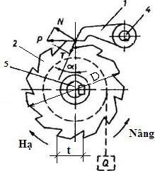
Figure 1.50 Ratchet
The circular force distribution has two components: the force distribution perpendicular to the tooth surface P.cosα and the tangential force distribution P.sinα, under the effect of this force the ratchet moves to the bottom of the tooth. In which, the friction force arises at the contact surfaces: F = fN = f.Pcosα
From there: tgα > f = tgρ with ρ being the angle of friction.
o
The average value f = 0.20 corresponds to α = 11. If we take into account the surface's ability to
o
damage, dirt and friction at the ratchet shaft should usually take α = 20.
The ratchet body is calculated according to the compressive and bending strength. The maximum stress arises when the pin starts to engage at the critical cross-section:
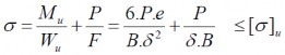
In there:
- B: Thickness of latch.
- δ: Height of the cross section under consideration.
- e: Distance from the center of gravity of the section under consideration to the line of action of the circular force P through the center of the pivot axis.
e = (0.4 ÷ 0.5)h
- [ζ]
u
2
= (60 ÷ 65) N/mm
: allowable bending stress of the material used to make the latch.
The diameter of the ratchet shaft d is calculated according to the bending strength condition:
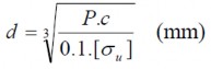
In there:
- [ζ ]: allowable bending stress of the ratchet shaft
u
- c: distance from the center of the cross section of the latch to the latch support
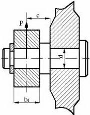
Figure 1.51: Pin in ratchet mechanism
1.6.2. Braking torque in lifting mechanism
All lifting mechanisms are equipped with brakes. The brakes here are usually electromagnetic or electro-hydraulic and are normally closed. That is, when the mechanism shaft is not rotating, the brake is closed, only when the mechanism shaft rotates will the brake automatically open.
Thanks to the brake, the mechanism is able to stop precisely. In the lifting mechanism, the brake can also help to actively adjust the speed of lifting and lowering objects.
Calculate braking torque.
To be able to calculate or select the appropriate brake, it is first necessary to calculate the value of the braking torque required to act on the mechanism to stop the mechanism.
The simplest is that the torque generated by the brake must be at least greater than the torque on the shaft of the brake lever mechanism, meaning: M p ≥ M x
In there:
- M p : Braking torque required to stop the mechanism.
- M x : Torque on the brake lever shaft.
However, in practice it is necessary to calculate the necessary braking torque, which is greatest when the mechanism lifts and lowers objects because this is the most dangerous case.
To determine the braking torque, consider the process of lowering the object in the lifting mechanism, in the figure below.
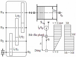
Figure 1.52: Brake torque calculation diagram
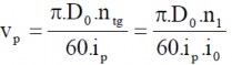
The output of the reducer is fitted with a cable drum of diameter D o . The cable carrying the load is suspended through a movable pulley, this structure is a positive pulley with a coefficient of η p .
When lowering an object, the braking torque consists of two components:
- Static moment M t is caused by the weight of the object. Static moment acts during the entire time when lowering the object at constant velocity, during the braking time when lowering the object.
- Dynamic moment M is caused by the kinetic energy of the object and rotating parts of the mechanism, due to the velocity gradually decreasing to zero. Dynamic moment only appears when braking (see dynamic load section).
Thus: M p = M t + M đDetermine the static moment M t . Tension force on the soft element:

The torque needed to lift the object acting on the drum:
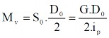
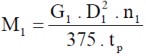
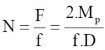
When the brake is applied to the input shaft 1 of the mechanism, the moment exerted by the weight of the object on this shaft is:
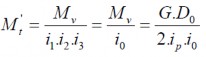
i = i .i .i : Overall transmission ratio of the gearbox.
0 1 2 3
The harmful resistance of the hoist, drum and transmission acts as a brake and reduces the static moment M t '. Therefore:
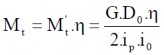
In which: η = η .η .η .η .η – Overall efficiency of the structure.
P tg 1 2 3
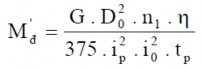
Determine the dynamic moment M
The dynamic moment M has two components: M = M + M + '' In which:
- M đ ': Moment created by the kinetic energy of the object when it stops.
- M đ '': Moment caused by the kinetic energy of the rotating parts of the mechanism.
To determine Mđ ' , consider the braking process as a process of uniform deceleration. According to the Dalambare principle, then the secondary load generated on the hook has the value:

S p creates an additional moment on the drum:
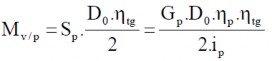
And S p causes a dynamic torque on motor shaft 1 (Brake shaft):
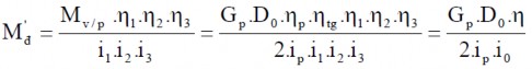
Substitute G p and v p into the above formula:

we have:
M đ '' is caused by the kinetic energy of the rotating machine parts of the mechanism on the brake shaft, and is also due to the dynamic moment of all shafts of the mechanism converted to brake shaft 1.
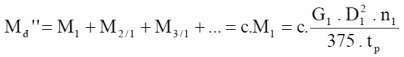
M đ '' = M + M + M + …
1 2/1 3/1
Moment M is the dynamic moment due to the mass of shaft 1 and of the parts mounted on the shaft.
1
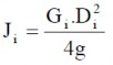
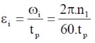
1 caused by gradual slowing down: M = J .ε General: Mi = J .ε
1 1 1 ii
In there:
- Moment of inertia of all masses rotating on axis 1
- Angular acceleration of the 1st shaft during braking.
So:
Moment M is the dynamic moment due to the mass of shaft 2 and of the parts mounted on the shaft.
2
2 due to slow rotation causes the same determination as above:
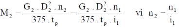
Bringing it back to axis 1 (brake axis), we get:
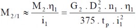
Similar to above we can determine:
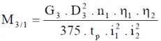
Comparing the values of M 1 , M 2/1 , M 3/1 , ..., we can see that the later the moment value is, the smaller it is compared to M 1 . The total of the later moments is usually not more than 15% of M 1 , so let
simple when calculating M ' usually only calculate M , the influence of the remaining moments
1
replace with value c = (1.10 ÷ 1.15).
When determining the total flywheel moment value of shaft 1 mass (fast rotating shaft), it is important to note that its main component is the flywheel moment of machine parts with large weight G and large diameter D, which are: electric motor rotor, coupling and brake wheel, while the flywheel moment of the shaft itself has a small, insignificant value and can be ignored.
Therefore:

M
Thus, the general expression to calculate the braking torque has the form: M p = M t + M đ' +
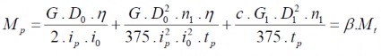
The coefficient β is called the safety factor of the brake.

In the preliminary calculation, β is selected based on the working mode: For light working mode NH, β ≥ 1.50; for medium working mode TB, β ≥ 1.75; for heavy working mode N, β ≥ 2.00.
1.6.3. Brake pads
Because of its many advantages, brake pads are widely used in the lifting industry. Brake pads can be divided into two types: single-pad brake and double-pad brake. The pressure exerted on the shaft of the mechanism by the double-pad brake is more even than the single-pad brake, so in the lifting mechanism, only double-pad brake is used.
a. One-piece brake
Figure 1.53 shows the simplest single-pad brake diagram. Brake disc 1 is mounted on the brake lever shaft, brake pad 2 is mounted on the brake lever 3, which rotates around the joint.
O. Disk 1 can rotate in two directions. When pressing the lever head 3, jaw 2 presses against disk 1, thanks to friction force F the mechanism stops.
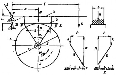
Figure 1.53: Calculation diagram of 1-pad brake
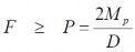
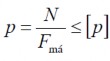
The disc has diameter D, the rotational force caused by the torque on the shaft of the mechanism is P. Conditions for the mechanism to stop when braking:
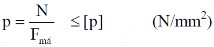
The required compressive force N on the brake disc to create frictional force F is:
In which: f is the coefficient of friction between the brake pad and disc.
To reduce the compressive force, the coefficient of friction f must be increased. Normally, materials with high coefficients of friction such as phenol, aberto, etc. are used to rivet or glue to brake pad 2. In the forklift, the brake is usually placed on shaft 1, using the coupling disc as brake disc 1.
For the brake to work, not overheat beyond the allowable limit and not wear out quickly, the following conditions must be met:
(1.5) |
Maybe you are interested!
-

 Assessment of the World Trade Organization's Dispute Settlement Mechanism for Developing Countries
 -
 Perfecting the financial mechanism for science and technology activities in universities in Vietnam - 8
 -
 Current Status of Financial Mechanism for Science and Technology Activities in Universities in Our Country
 -
 Study of rainbow effect and alpha transfer mechanism in low and medium energy scattering - 2
 -
 Some solutions to implement the self-declaration and self-payment tax management mechanism in Binh Thuan province - 10
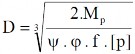
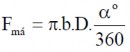
In there:
- F brake pad = bS: Working surface area of brake pad.
- b = θ.D: Brake pad width, coefficient θ = 0.3 ÷ 0.4.
- S = ψ.D: Brake pad length, coefficient ψ = 0.5 ÷ 0.7.
- [p]: Allowable specific pressure, with the pherado taking the value 2 ÷ 2.2 N/mm 2 .
Substituting the values of N and F mas into (1.5) and transforming, we get the formula to determine the diameter of the brake disc:
Determine the length of the brake pad S
The length of the brake pad is determined from the heating condition: pfv ≤ [A] In which:
- pv: Specific work of friction force.
2
- [A] = 150 ÷ 200 (N.mm/mm): Allowable work.
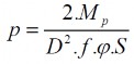
Specific pressure value:
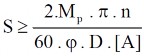
The linear speed of the brake disc, corresponding to the number of revolutions n (rpm):

Putting the values of p, v, f and [A] into (1.5) and transforming, we get:
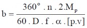
Determine the width of the brake pad b
Brake pad width b is calculated according to the allowable specific pressure: From the formulas:
Where α is the angle between the brake pad and disc. We get:
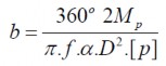
Or the width b is determined from the heating condition:
pv ≤ [pv]
Substitute the values of p and v, transform and we get:
Determine the braking force K
From the stopping condition
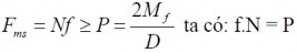
we have: fN = P