Chapter 3. FX5U PLC COMMAND SYSTEM
3.1. Command groups for CPU
3.1.1. Sequence Instruction
Ladder | ST | FBD |
| As Ladder |
Maybe you are interested!
-

 Mitsubishi PLC Programming Guide - 3
 -
 Evaluation of the effectiveness of brain protection in comatose patients after circulatory arrest by command hypothermia - 25
 -
 Current Status of Tourism Connection Between An Giang and Neighboring Regions
 -
 Evaluation of the effectiveness of brain protection in comatose patients after circulatory arrest by command hypothermia - 2
 -
 Designing teaching activities for the lesson Parallel force rule. Equilibrium conditions of solids under the action of three parallel forces and the lesson Caucasus's law. Absolute temperature Advanced Physics 10 textbook to promote students' initiative and autonomy in learning - 9
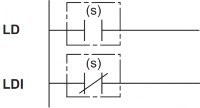
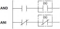
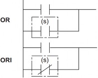
1. Initialization command, serial connection, parallel connection Command name: LD, LDI, AND, ANI, OR, ORI
Command data:
Function, value range, data type:
Operand
Function | Value range | Data type | Data type (label) | |
(S) | Used as a contact | Bit |
Operand type:
Operand
Bit | Word | Double word | Constant | ||||
X, Y, M, L, SM, F, B, SB, S | T, ST, C, D, W, SD, SW, R | Z | LC | LZ | K, H | E | |
(S) | |||||||
LD: Command to initialize logic value of normally open contact type NO;
LDI : Command to initialize logic value of normally closed contact type NC;
These commands will follow the ON/OFF state of the contact and use this result as an active result to serve other commands.
AND: Serial command with normally open contact NO. Use this result as the operation result.
ANDI : Serial instruction with normally closed contact. Use this result as the operation result.
OR: Parallel connection command with normally open NO contact. Use this result as the operating result.
ORI : Parallel connection command of NC normally closed contacts. Use this result as the operation result.
Ladder | ST | FBD |
| ENO:=LDP(EN,s); ENO:=LDF(EN,s); ENO:=ANDP(EN,s); ENO:=ANDF(EN,s); ENO:=ORP(EN,s); ENO:=ORF(EN,s); |
|
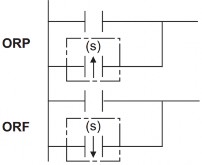
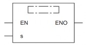
2. Pulse initialization command, pulse serial connection, pulse parallel connection. Command name: LDP, LDF, ANDP, ANDF, ORP, ORF
LDP: A rising edge logic bit initialization instruction. Indicates immediately upon the rising edge of the bit device(s). When Word devices are specified by subbits, this contact indicates immediately upon the state of the bit changing from 0 1.
LDF: Rising edge logic bit initialization instruction. Indicates immediately upon the rising edge of the bit device(s). When word devices are specified by subbits, this contact indicates immediately upon the state of the bit device changing from 1 to 0.
ANDP : Serial command with LDP rising edge capture contact specified by bit device(s). ANDF : Serial command with LDF falling edge capture contact specified by bit device(s) ORP : Parallel command with LDP rising edge capture contact specified by bit device(s)
ORF: Parallel connection command with LDF falling edge contact identified by device bit(s)
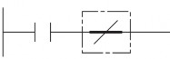
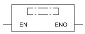
3. NOT pulse initialization command, serial connection with NOT pulse, parallel connection with NOT pulse
Command name: LDPI, LDFI, ANDPI, ANDFI, ORPI, ORFI
Ladder
ST | FBD | |
|
| ENO:=LDPI(EN,s); ENO:=LDFI(EN,s); ENO:=ANDPI(EN,s); ENO:=ANDFI(EN,s); ENO:=ORPI(EN,s); ENO:=ORFI(EN,s); |
|
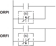
LDPI: The command does not conduct when there is a rising edge. The contact only stops conducting immediately when there is a change in state from 0 to 1 of the bit device (s).
LDFI: The instruction does not conduct when there is a falling edge. The contact only stops conducting immediately when there is a change in state from 1 to 0 of the bit device (s).
ANDPI: Serial connection command with LDPI contact
ANDFI: Serial connection command with LDFI contact
ORPI : Parallel connection command with LDPI contact
ORFI: Serial connection command with LDFI contact
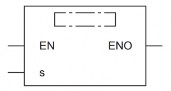
4. Ladder block serial/parallel connection command
Command name: ANB, ORB
Representation in programming languages
Ladder
ST | FBD | |
|
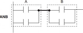
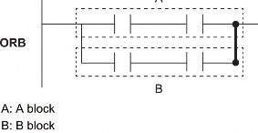
ANB: AND command for two blocks A and B together
The symbol for this command is not a NO symbol but a connection symbol.
ORB: OR command to OR two blocks A and B together
5. Branch command
Command name: MPS, MRD, MPP
Representation in programming languages
Ladder
ST | FBD | |
| ENO:=MPS(EN); ENO:=MRD(EN); ENO:=MPP(EN); |
|
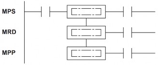
MPS: Stores the current results of operations inside the PLC. This instruction can be used up to 16 times in a row. When the MPP instruction is used in the middle, the number of usable instructions of the MPS instruction is reduced by 1.
MRD: reads the current results of the operations inside the PLC.
MPP: retrieve and clear current storage results.
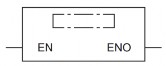
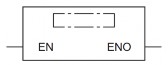
6. Invert result command
Command name: INV
Representation in programming languages
Ladder
ST | FBD | |
| ENO:=INV(EN); |
|
This command allows to reverse the result of the previous command operation.
Data input to INV command
Data goes to INV command | |
ON | OFF |
OFF | ON |
7. Convert the operation result into pulse
Command name: MEP, MEF
Representation in programming languages
Ladder
ST | FBD | |
| ENO:=MEP(EN); ENO:=MEF(EN); |
|
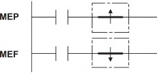
MEP: This instruction is ON on the rising edge of the current value and OFF in other cases.
Use this command to invert pulses easily when multiple contacts are connected together.
MEF: This instruction is ON on the falling edge of the current value and ON otherwise. '
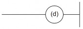
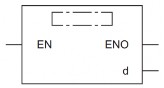
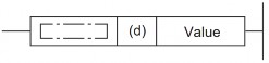
8. Out Commands (except Timer, Counter and Annunciator)
Command name: OUT
Representation in programming languages
Ladder
ST | FBD | |
| ENO:=OUT(EN,d); |
|
Function, value range, data type:
Operand
Function | Value range | Data type | Data type (label) | |
(d) | Number of on/off devices | Bit | ANY_BOOL | |
EN | Conditions of execution | Bit | BOOL | |
ENO | Execution results | Bit | BOOL |
Work
This command outputs the current value to the specified devices.
Condition
Current value | Coil/Bit Identification | |
When Bit device is used | OFF | OFF |
ON | ON | |
When Bit of Word is used | OFF | 0 |
ON | 1 |
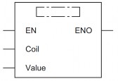
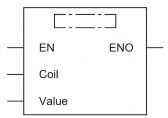
9. Timer (low-speed, high-speed, low-speed with memory, high-speed with memory)
Command name: OUT T, OUTH T, OUTHS T, OUT ST, OUTH ST, OUTHS ST
Representation in programming languages
Ladder
ST | FBD | |
| ENO:=OUT_T(EN,Coil,Value); ENO:=OUTH(EN,Coil,Value); ENO:=OUTHS(EN,Coil,Value); |
|
Function, value range, data type:
Operand
Function | Value range | Data type | Data type (label) | |
(d) | Timer Name | Timer/ timer with memory | ANY | |
value (set value) | Time to order | 0 to 32767 | 16-bit unsigned | |
EN | Conditions of execution | Bit | BOOL | |
ENO | Execution results | Bit | BOOL |
The timer will count up according to the set value. When the current value reaches the set value, the coil of the Timer/Timer with hold (d) will be turned on. At that time, the normally open contact NO will conduct and the normally closed contact NC will stop conducting.
When the current value of the OUT command changes from ON to OFF, the operation of the contacts will be as shown in the following table.
Timer Type
Timer coil | Current value of Timer | Before time-out | After timer-out | |||
NO contact | NC contact | NO contact | NC contact | |||
Timer | Off | 0 | No lead | Guide | No lead | Guide |
Retentive remember | off | Keep current value | No lead | Guide | Guide | No lead |
Times-up: When the Timer counts up to the set value.
After the Timer Times-up, clear the current value of the Holding Timer and turn off the contacts using the RST reset command.
When the value is set to 0, Times-up occurs as soon as the OUT instruction is executed.
The value used for the Timer can be set in the range 1 32767. Since the OUT, OUTH and OUTHS instructions operate on 100 ms, 10 ms and 1 ms timers respectively, the real time constants will be as follows:
• OUT : 0.1 to 3276.7 seconds
• OUTH : 0.01 to 327.67 seconds
• OUTHS : 0.001 to 32.767 seconds
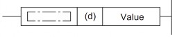
10. Counter, Long Counter
a. Counter
Command name: OUT C
Representation in programming languages
Ladder
ST | FBD | |
| ENO:=OUT_C(EN,Coil,Value); |
|
Function, value range, data type:
Operand
Function | Value range | Data type | Data type (label) | |
(d) | Digital timer (Timer name) | Counter | ANY | |
(set value) | Set value | 0 to 32767 | 16-bit unsigned | |
EN | Conditions of execution | Bit | BOOL | |
ENO | Execution results | Bit | BOOL |
The OUT C instruction increases the current value of the counter specified by (d) by 1 when the current value by the OUT instruction changes from OFF to ON, and when the counter reaches the set value, the NO contact will conduct and the NC contact will stop conducting.
The counter will not count while the current value is held in the ON state (The count input does not necessarily have to be pulsed).
After counting to the set value, the count value and contact status will not change until the RST command is executed.
When the set value is 0, the same handling as when the set value is 1 is performed.
b. Long Counter:
OUT LC instruction name. The instruction increases the current value of the counter specified by (d) by 1 when the current value according to the OUT instruction changes from OFF to ON, and when the counter reaches the set value,