2.1.3. Unprotected steel-concrete composite floor slab
Steel-concrete composite floors are widely used. During construction, concrete is poured directly onto corrugated iron sheets, which act as both load-bearing and formwork. The basic advantage of this type of structure is convenience and time-saving construction. Depending on each specific project, the floor slab can be constructed with simple or continuous supports.
When studying the fire-resistant working state, it is assumed that the sheet metal is not insulated, heated under the direct impact of the flame and there is no insulation between the concrete floor and the surface concrete layer. Therefore, the temperature in the sheet metal will increase very quickly, automatically deform and is considered to work independently of the concrete part. In traditional calculation views, people ignore the load-bearing participation of the sheet metal in fire-resistant conditions.
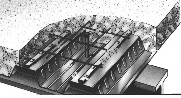
Figure 2.1: Image of floor panels [9]
However, in reality, corrugated iron sheets play a very important role, they act as a hard plate to prevent fire and smoke from passing through, reduce the rate of heat transfer in concrete and have the effect of limiting the phenomenon of cracking and breaking concrete. Therefore, the E standard for tightness is always satisfied for this type of structure.
Because the influence of the corrugated iron sheet is not taken into account, the steel reinforcement plays the main load-bearing role, the floor slab is calculated as a normal reinforced concrete slab but bears thermal loads. The floor slab will be destroyed when the stress in the steel reinforcement reaches the yield limit. Concrete has the task of insulating the steel reinforcement and controlling the heat transfer process through the floor slab. Using lightweight aggregate concrete to perform the above two roles has many advantages over normal concrete, in addition, the rate of strength loss of lightweight concrete is also slower. Thus, the corrugated iron sheet, steel reinforcement and concrete all have their own functions, people have studied the overall performance of the structure according to two standards I and R. The thesis only presents the standard R
* R Standard:
Under the influence of high temperature, the mechanical properties of the material are reduced, causing both the strength and the bending stiffness of the floor slab to decrease. In fact, due to the high heat resistance of concrete and the escape of water vapor on the concrete surface, the temperature of the corrugated iron sheet is always lower than the temperature of the fire. Therefore, in many cases, the influence of the corrugated iron sheet is not considered when calculating the fire resistance. In many cases, when the corrugated iron sheet is fixed at the support (through pins connected to the beam) or when the corrugated iron sheet is arranged in the part of the floor slab with a lower temperature (when the floor slab is large in size, the temperature distribution in the floor is uneven), the axial deformation of the corrugated iron sheet is limited, causing the floor slab to be restrained in its plane. As a result, the membrane stress in the floor increases and increases the fire resistance of the floor slab.
According to the simple calculation method, when bearing force under fire conditions, the neutral axis of the floor slab is determined from the stress balance equation:
f f
∑ A k
ay,i 0.85∑ A k
c, j
i
In there:
y , , i
M , fi,a
jc , , j
M , fi,c
f ay , i / M , fi , a : are the calculated strength of the steel area Ai under normal temperature conditions, taking positive values for the compression part and taking negative values for the tensile part of the floor slab cross section.
f c , j / M , fi , c : are the calculated strengths of the concrete area Aj under normal temperature conditions, only taking positive values (because the tensile concrete work is ignored).
ky , ,i
and k c , , j
is the strength reduction coefficient of steel and concrete materials
when working in fire-resistant conditions.
Then the moment resistance of the floor slab has the value:
f f
M ∑ A k
ay ,i 0.85∑ A k
c, j
iy , ,i
M , fi,a
jc, , j
M, fi, c
Where z i and z j are the distances from the neutral axis to the centroids of the areas A i and A j respectively.
For the structure to satisfy the durability condition, the calculation value is based on the load in fire.
must be less than this moment capacity, i.e.
M fi,Sd
M fi,Rd . Problem statement
We have to analyze the heat, determine the temperature distribution in each part of the slab cross section corresponding to specific load-bearing cases:
- When calculating the positive moment resistance of the floor slab, not only the corrugated iron sheet but also the tensile concrete part is ignored. If the structural requirements for insulation are satisfied, the temperature of the structural part not directly exposed to fire is low, so the compressive concrete part is considered to have no loss of strength. The tensile reinforcement content and the temperature of the reinforcement will determine the positive moment resistance of the floor slab. This temperature depends on
distance from the heated surfaces to the reinforcement, expressed as a position function “ z ”:
1 1


z u1
1 1


u2 u3
With ui being the perpendicular distances from the steel bars to the edges of the corrugated iron sheet (in terms of structure, u1 and u2 50mm; u3 35mm)

c c1u3 cz c3 A c c5


(0C)
h
H
l
s 0 2 4
2 p 3
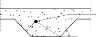
In which is the angle of inclination of the web of the sheet metal compared to the horizontal direction.
u1 u
u 3 2
Steel cut
u1 u 2
u
3
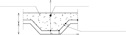
Figure 2.2: The ui distances to determine the z position function [13]
The coefficients c i are given in the following table, depending on the aggregate composition of the concrete and the required fire resistance level:
Durability | c0 | c1 | c2 | c3 | c4 | c5 | |
Concrete | Fireproof | (0C) | (0C) | (0C.mm1/2) | (0C.mm) | (0C/0) | (0C.mm) |
R60 | 1191 | -250 | -240 | -5.01 | 1.04 | -925 | |
R90 | 1342 | -256 | -235 | -5.30 | 1.39 | -1267 | |
R120 | 1387 | -238 | -227 | -4.79 | 1.68 | -1326 | |
R60 | 1336 | -242 | -292 | -6.11 | 1.63 | -900 | |
R90 | 1381 | -240 | -269 | -5.46 | 2.24 | -918 | |
R120 | 1397 | -230 | -253 | -4.44 | 2.47 | -906 |
Maybe you are interested!
-

 Determining the Competitive Position of Tourism Products and the Appropriate Growth Strategy
 -
 Position, Role, Function of Primary School Principal in Management
 -
 Determining the Composite Score to Assess the Skills of Preschool Children Participating in the Test
 -
 Determining the Position and Role of Ecotourism Industry
 -
 Method for Determining Properties and Structure of Blend Rubber Materials
Table 2.1: Ci values corresponding to normal concrete and lightweight concrete [13]


Regular concrete


Lightweight concrete
When calculating the negative moment resistance, we still ignore the work of the corrugated iron sheet and the tensile concrete part. Because the compressive concrete part is directly exposed in
fire, so we must consider the reduction in the design cross-section. In this case, we calculate the limiting temperature value lim:
lim = d0 + d1Ns + d3 + d2A/Hp + d4/l3 (0C)
In there:
Ns = As . fay is the tensile force of the tensile reinforcement
With coefficient d i depending on the aggregate composition of the concrete and the required fire resistance level.


Table 2.2: Di values corresponding to normal concrete and lightweight concrete [13]
Concrete
Durability Fireproof | d0 (0C) | d1.10-4 (0C.N) | d2 (0C.mm) | d3 (0C.mm) | d4 (0C.mm) | |
Regular concrete | R60 R90 R120 | 867 1055 1144 | -1.9 -2.2 -2.2 | -8.75 -9.91 -9.71 | -123 -154 -166 | -1378 -1990 -2155 |
Lightweight concrete | R60 R90 R120 | 1030 1159 1213 | -2.6 -2.5 -2.5 | -10.95 -10.88 -10.09 | -181 -208 -214 | -1834 -2233 -2320 |


From the state of heat distribution on the cross-section of the floor slab, we draw an isotherm, connecting all points with the limiting temperature lim (ie the part lying on this isotherm). The isotherm is determined through 4 cross-sections
Total calculation part
h1
Y
Tensile steel bar
(3) (4)
h2 (1) (2)

l2
l3 /2 l1
Isothermal curve lim
X
l3 /2

Figure 2.3: Determination of isotherm = lim [13]
+ Point 1: point located in the middle of the corrugated iron wave, a distance from the lower flange of the corrugated iron sheet determined by the 2 coordinate values X1 and Y1
X1 = 0;
Y1
1
1
4
l1 l3
z
where z is calculated from the equation
2
Determine the temperature of the steel s when assuming u3/h2 = 0.75 and s = lim
+ Point 4: point located between two corrugated iron waves, a distance from the upper flange of the corrugated iron sheet determined by the two coordinate values X4 and Y4
X 4
1
2 l 1
1
2 l 3
; Y4
h2 b
where b
1
2 l 1
a2 4a c
sin 1
a
With arctan
2 h 2
1
; a
2
1
l sin
h2
l l z 1
1 2
c 81
1 a when
a 8 and
c 81
1 a when
a 8
+ Point 2: lies on a horizontal line, at the same height as point 1, at a distance from the web of the sheet metal equal to the distance from it to the lower flange.
1 Y 1
X 2 2 l 2 sin cos 1; Y 2 Y 1
+ Point 3: lies on a horizontal line, at the same height as the upper flange of the sheet metal, at a distance from the web equal to the distance from point (4) to the sheet metal.
upper wing: X
1 l
b ; Y h
3 2 1
sin 3 2
In this case, the top concrete contains tensile reinforcement and the temperature of the reinforcement will determine the negative moment resistance of the slab. The temperature of the tensile reinforcement can be taken as the temperature of the concrete at the location of the reinforcement.
2.1.4. Steel-concrete composite beams Composite beams without concrete cover:
Under fire conditions, since the steel beam section is not protected, there is a significant temperature difference between the upper flange (the part connected to the concrete floor slab) and the lower flange (the part directly exposed to fire). This has a great influence on the flexural capacity of the composite section.
a. Case of positive moment:
- When the concrete slab has a thickness greater than 120mm, the steel beam has a cross-sectional height less than or equal to 500mm, we assume that the temperature is evenly distributed over the steel beam cross-section and use the critical temperature method. The structure satisfies the load-bearing requirements under fire-resistant conditions when fi,t cri,t
Then, fi,t is the load reduction factor when considering the influence of the load types acting on the structure.
applied to structures under fire conditions is determined:
fi,t
E fi,d ,t
Rd
In there:
Efi,d,t: is the result of calculating the impacts at time t under fire resistance conditions.
Rd: is the calculated strength of steel material at temperature conditions
often.
In the critical state, when the temperature in the structure reaches crit, E fi,d,t = R fi,d,t where R fi,d,t is the calculated strength of the steel material at time t under fire-resistant conditions.
E fi,d ,t
R fi,d ,t
R
fa max,cr / M , fi,a
R
fi,t
dd
fay,200 C
/ M ,a
yes,20CM,a
f 0 / : is the calculated strength of steel under temperature conditions
usually at 200C
f a max, cr / M , fi , a : is the calculated strength of steel under fire resistance conditions
This has proven that the compressive working state of concrete does not greatly affect the flexural capacity of composite beams under fire conditions. Because the lower flange and web are directly exposed to fire, the strength is rapidly reduced, so the tensile capacity of the steel beam is quite small. Therefore, the neutral axis position of the composite beam section is located in the concrete floor slab and only a small part of the floor concrete is under compression. Thus, the positive moment capacity of the section is determined by the working state of the steel beam section. In practice, M,fi,a=1 ; M,a=1,1 .
fi,t
R fi,d ,t
Rd
fa max,cr
,20
0.9 f 0
ay C
or 0.9 fi,t
fa max,cr ay,20 C
f 0
- When the steel beam is higher than 500mm, the floor slab is smaller than 120mm, we use the moment method, calculating according to the plastic working state of the material. The temperature distribution in the cross section is shown in Figure 2.8: including the temperature of the upper flange 2, the temperature of the web w and the temperature of the lower flange
1. During the allowable fire resistance period, the neutral axis position is determined
determined from the balance of tensile forces T in the lower part and compressive forces F in the upper part of the section.
The calculated width of the slab is determined in the same way as in the case of composite beams under normal conditions. Assuming that the neutral axis is located in the concrete slab, at a distance h from the upper edge of the slab , the compressive force of the concrete is calculated according to the formula:
f 0 hb
F ay , 20 C u ef
M, fi, c