Construction of Van Hien University (Binh Chanh) and the second subsidence monitoring point at Binh Hung Wastewater Treatment Plant (Binh Chanh) to serve as a basis for comparison and calculation.
2.5.1. Deep settlement monitoring equipment
The system includes PVC pipes with an inner diameter of 24.5mm and an outer diameter of 33.5mm, telescope tubes, magnetic spiders and magnetic tables. The pipe sections are connected together by connecting tubes, magnetic spiders, and telescope tubes will be attached to the pipes according to the design drawings. Measure the height of the magnetic spiders to measure the vertical displacement of the ground. Telescope tubes, also known as collapse tubes, are designed so that when the ground subsides, the PVC pipes will be limited from being compressed and damaging the PVC pipes, figure 2.9.
The initial reading will be taken after the mortar has set and the spiders have stabilized under their own weight.
Spider from
Depth gauge
Figure 2.9: Deep settlement monitoring equipment and auxiliary equipment
2.5.2. Installation of monitoring equipment
a. Steps to take
Prepare construction site, about 15m2 , with convenient equipment movement route.
Determine the installation location and drill a 110mm diameter hole to the required depth of about 25 - 27m. Clean the drilling cuttings.
Number different pipe sections for installation, fix the spiders on the pipe sections at the required depth. Label the spider wires and pipe sections.
Lower the grouting pipe and measuring pipe to the bottom of the borehole. Connect the next pipe sections, seal the spider wire connections from the carefully held and lower the pipe into the borehole. Arrange the spider wire appropriately so that the spider legs do not come loose. Continue adding and lowering the pipe connections to check the spider depth.
Start pumping the mortar - water - bentonite mixture with a ratio suitable for the strength of the soil, when the mortar rises to the spider's feet, pull the spider release rope. Continue pumping mortar until all spiders are released, pump mortar until the borehole is full.
Use PVC pipes with larger diameters for external protection to ensure that the pipes can move freely during ground subsidence.
Monitor the depth of settlement using a settlement gauge and a level. The settlement gauge is made with a chip that can make a sound when it encounters a spider.
The spider and the magnetic table are measured by lowering the probe of the measuring ruler into the measuring tube, when hearing the sound, determine the depth of the spider. To avoid errors during the measurement process, it is necessary to unify the measurement method, which is to measure from bottom to top or from top to bottom, the top of the tube must be level and the ruler must be kept parallel to the tube wall to get the most accurate reading.
The settlement of the spider is calculated from the elevation of the top of the tube and compared with the initial reading.
Some images of the construction and installation process of deep settlement monitoring equipment:
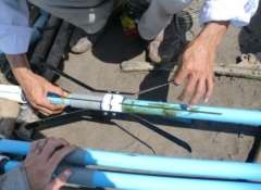
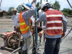
Figure 1. Install the magnetic spider into the PVC pipe Figure 2. Drill and install the pipe
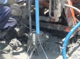
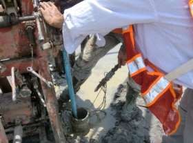
Figure 3.. Grouting Figure 4. Pulling out the spider pin wire from
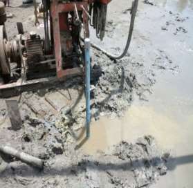
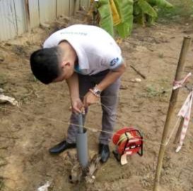
Figure 5. Completion of installation of deep settlement monitoring pipe
Figure 6. Completed ground plan and settlement measurement at Van Hien University on November 1, 2017
Figure 2.10: Some images of the installation process of the depth measuring device (details are shown in Appendix 03_Image Appendix)
b. Installation location
Within the scope of the study, the author selected 02 monitoring locations shown in table 3.6, page 48 with two monitoring points as follows:
+ QT1: Located in the southwest of the project. About 150m south of Nguyen Van Linh Street and 40m east of the high-rise apartment building. The area was leveled and raised in 2016 but there is no infrastructure construction yet. The image shows the deep monitoring location as shown in Figure 2.11.
Monitoring location
The area is
build
Figure 2.11: QT1 deep settlement monitoring location
+ QT2: Located south of the existing water treatment plant. 20 - 40 m north of the phase 2 construction area. The area is under construction so heavy trucks often enter and exit. The area was filled in 2009 with a sand layer thickness of nearly 8.0 m.
2.5.3. Time of observation and recording of results
Use a depth gauge to measure the reading of the magnetic table and installed magnetic spiders, with the pipe mouth as the reference point.
a. Monitoring period : 12 months from the date of equipment installation. The specific monitoring schedule is presented below:
Monitoring period: November 2017 - October 2018. Table 2.8: Table showing the time of deep settlement monitoring
STT
Observation date | QT1 | QT2 | Note | |
1 | 11/1/2017 | |||
2 | November 8, 2017 | |||
... | .... | |||
17 | October 31, 2018 |
Maybe you are interested!
-

 Completing the management and supply of raw materials at the training equipment manufacturing factory X55 - 7
 -
 Results in Increased Knowledge and Skills in Self-Monitoring Blood Pressure
 -
 Indirect Monitoring Through Incentives:
 -
 Current Status of Facilities Management, Ensuring Equipment for Self-Study Activities
 -
 Completing the management and supply of raw materials at the training equipment manufacturing factory X55 - 5
Master's thesis: "Research on subsidence in the South Saigon area"
b. The results are recorded in the table as follows : Table 2.9: Table recording the results of deep subsidence monitoring
SEDIMENT MONITORING RESULTS
MEASUREMENT DATE
LOCATION | SPIDER | FIRST TIME | 2ND TIME | 3rd TIME | ||||
TITLE 1 | TITLE 2 | TITLE 1 | TITLE 2 | TITLE 1 | TITLE 2 | |||
11/01/2017 | QT1 | N1 N2 N3 N4 | ||||||
QT2 | N1 N2 N3 N4 | |||||||
24.01.2018 | QT1 | N1 N2 N3 N4 | ||||||
QT2 | N1 N2 N3 N4 | |||||||
HVCH: Vo Minh Quan _ MSHV: 1570200
62
In short:
The thesis uses the method of collecting, analysing and analyzing geological survey drilling data and research results in the area to create a database as a basis for developing other research methods. This includes the method of editing maps to build a typical geological cross-section of the area as well as selecting locations for current status surveys and deep subsidence monitoring.
The theoretical settlement calculation method mainly uses the experimental results of physical and mechanical indicators at boreholes and the load acting on the ground to calculate the actual settlement results and analyze future settlement. The method of monitoring ground settlement with 20 survey points to collect the results of ground settlement that have occurred in the area. The method of monitoring deep settlement using magnetic spider equipment is installed at 02 locations in the area and is measured regularly every week and month to collect the settlement developments that are taking place in the research area.
Each method produces different data on settlement, from the actual situation to current developments and future forecasts. These results are analyzed, compared and evaluated with each other to ensure reliability in determining and forecasting settlement in the study area.
However, more borehole data and surface settlement monitoring data are also needed, as well as more deep settlement monitoring equipment needs to be drilled and installed to build a wide monitoring network and meet high accuracy requirements.
CHAPTER 3. SEDIMENT ASSESSMENT
3.1. Results of building data set on mapinfo
The data set was compiled from geological survey reports, with a total of 243 boreholes collected. The borehole data was statistically compiled and processed in Excel before being imported into the software as a basis for analysis, calculation, and forecast of subsidence in the study area.
The data set shows the location of the boreholes on the map through the X and Y coordinates, which are compiled into an excel file. The location of the boreholes is accurately shown using the X and Y coordinates in the VN-2000 coordinate system, 105 degrees 45 minutes North (in meter length units).
Figure 3.1: Map showing the location of the collection borehole
In addition to showing the locations of the boreholes on the map of the study area, these borehole data also carry geological attributes at each borehole. For each borehole location, the data attributes are shown next to it, including: Symbol, elevation of the fill layer, borehole elevation, X, Y coordinates, static water level height. Collecting 243 boreholes, we have a table of attributes for each borehole, Figure 3.2.