* Input/output block
All internal signal processing in PLC has voltage levels of 5VDC and 15VDC (voltage for TTL and CMOS) while external control signals can be much larger typically 24VDC to 240 VDC with large currents.
The input/output block acts as a communication circuit between the PLC's electronic microcircuits and external high-power circuits that activate the actuators. It performs the conversion of signal voltage levels and isolation. However, the input/output block allows the PLC to connect directly to small-capacity actuators with currents of 2 Amp or less, without the need for intermediate power circuits or intermediate relays.
There are the following types of input and output:
Maybe you are interested!
-
 Procedure for Designing a PLC Control Program
 -
 Building a special tourism program for Hung Yen City - 2
 -
 Building a communication and promotion program for Nui Than Tai hot spring park - 9
 -
 Building a Research Model on Factors Affecting the Effectiveness of Internal Control System in Social Insurance Collection
 -
 Building a communication and promotion program for Nui Than Tai hot spring park - 7
Relay output type
Relay
Internal circuit
com
2A – 250VAC
2A – 24 VDC
Figure IV.2 Principle of mechanical relay output
Characteristic:
Can be connected to AC voltage operating mechanisms or is relay isolated so response is slow.
Life depends on the load current through the relay and the contact switching frequency.
Transistor output type
Relay
Circuit
in
com
50mA- 4.5V
300mA-24.6V
Figure IV. 3 Transistor output
Characteristic:
Only connect to the actuator working with DC voltage from 5 – 30V
Long life, fast response, withstand fast switching frequency.
Output type using Triac (SSR – Solid state relay)
Relay
Circuit
in
com
0.4A
100 240VAC
Figure IV .4 Output using triac
Characteristic:
Can be connected to the actuator working with DC or AC voltage from 5 – 242V
Withstands smaller currents than relay outputs but has a longer life and is more resistant to
Fast opening and closing frequency, fast input response.
One way entry
24VDC
10%
com
R
R
Circuit
in
Figure IV.5 One-way inlet
AC input
R
R
100-120VAC
+10%, -15% 100-120VAC
+10%, -15%
com
C
R
Circuit
in
Figure IV. 6 Alternating current input
All inputs are isolated from external control signals by an opto-isolator. The opto-isolator uses a light-emitting diode and a transistor called an op-coupler. This circuit allows small signals to pass through, and pins the voltage signals down to a reference voltage. This circuit provides protection against switching noise and overvoltage from the power supply, typically up to 1500V.
4.1.4 Procedure for building a control program
Learn the requirements of the control system
Connect all input and output devices to PLC
Construct a general flowchart of the control system
Check all wiring
List the inputs and outputs corresponding to the PLC inputs/outputs.
Translate flowchart to ladder diagram
Software Repair
Test run the program
Correct program?
Change program
Programming ladder diagram into PLC
Program simulation and software testing
Save program to EPROM
Organize all drawings systematically
Correct program?
End
Chapter V
Building a 4-storey elevator model
5.1 Model structure
5.1.1 Elevator shaft
This is the space limited by the bottom of the well, the surrounding walls and the ceiling of the well, in which the elevator cabin and counterweight move vertically, and is also the space for installing equipment specifically for the operation of the elevator such as shock absorbers, guide rails, and wire systems. The elevator shaft includes the elevator pit, the main shaft, and the top of the shaft.
- The shaft or elevator pit is below the floor of the lowest landing.
- Main shaft section: Is the space from the lowest floor to the highest floor.
- Top of the shaft: The top part of the shaft from the highest floor to the shaft ceiling.
Basic geometric dimensions of the elevator shaft:
- Well top height: 25 cm
- Elevator shaft depth: 120cm
- Elevator shaft width: 25 cm
- Floor door height: 10 cm
- Floor door width: 8 cm
- height of one floor: 25 cm
- Elevator pit depth: 20 cm
5.1.2 Guide rail
Guide rails are installed along the elevator shaft to guide the cabin and counterweight to move along the elevator shaft. The guide rails are firmly fixed to the load-bearing structure of the elevator shaft with screws.
5.1.3 Shock absorbers
Shock absorbers are installed at the bottom of the elevator shaft to stop and support the cabin, and
counterweight. In this model I do not use shock absorbers.
5.1.4 Cab and counterweight
The cabin model is manufactured including the cabin frame, cabin floor, cabin lights, cable suspension system and cabin door opening system located on the cabin floor.
Automatic door opening system: includes a DC motor controlled from the output of the PLC. When there is a command to open the door, the rotating motor will push the 2 levers to the 2 sides, these 2 levers contact the 2 tabs mounted on the cabin door, the cabin door will open. When there is a command to close the door, the motor will be controlled to rotate in reverse and
close the cabin
The counterweight is installed next to the cabin. The counterweight here is simply made using a metal plate. The lifting cable here is a cam chain. Because it runs in unloaded mode, the weight of the counterweight is equal to the weight of the cabin.
5.1.5 Structure of 4-storey elevator model
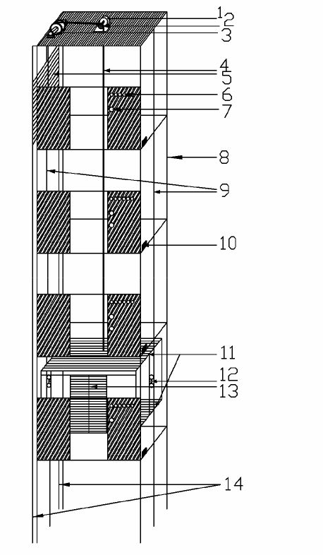
1 - Cabin traction motor 2 - Lip
3 - Chain guide pulley 4 - Cabin chain 5 - Counterweight
6 - Floor indicator light
7 - 8th floor call button - Elevator shaft
9 - Cabin guide rail 10 - Floor sensor
11 - cabin frame
12 - Cabin guide bracket 13 - Cabin door
14 - Counterweight guide rail
In the diagram above, we see that there is a sensor on each floor. When the elevator moves up or down until it meets the sensor on each floor, the PLC will send a command to cut off the power.
The engine and elevator cabin stop at the exact position requested by the caller.
In this model, motor adjustment is performed from the output of the PLC through the relay circuit switching. Motor adjustment goes up thanks to the contact with address Q0.0 and motor adjustment goes down thanks to the contact with address Q0.1. The elevator door is opened and closed through 2 contacts Q0.2 and Q0.3 combined with 2 door opening and closing sensors with addresses I1.0 and I1.1.
The indicator light system is installed outside the floor door through other outputs of
PLC.
5.1.6 Elevator control law
In the elevator, the floor call buttons are arranged outside the door of each floor, the floor buttons are placed in the elevator car, the floor call and floor arrival signals are completely random without any rules, so the technological requirement is to meet the requirements.