- Adjust the power supply frequency to the motor using thyristor or transistor frequency converters.
The disadvantage of asynchronous motors is that when the grid voltage drops, the starting torque and the critical torque will decrease a lot because the torque is proportional to the square of the voltage.
2.2 Commonly used drive systems in elevators
When designing the elevator drive system, the following factors must be considered:
Maybe you are interested!
-
 PLC System Industrial Electricity Profession - College Level - Petroleum College 2020 - 8
 -
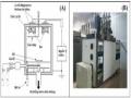 (A) Schematic Diagram of DC Sputtering System; (B) Image of Sputtering System at Itims Institute.
 -
 The Nature and Role of the Internal Control System
 -
 Some Solutions to Improve the Legal System of Alimony
 -
 Model system to assess the suitability of Vietnam's population-economic development process - 21
- Stopping accuracy.
- Elevator cabin movement speed.
- Maximum allowable acceleration.
- Speed adjustment range.
AC electric drive systems using asynchronous motors with squirrel cage rotors and wound rotors are commonly used in elevator drives. Asynchronous motors with squirrel cage rotors are often used for low-speed freight elevators. AC drive systems using asynchronous motors are often used for medium-speed elevators. DC drive systems with intermediate amplifiers are often used for high-speed elevators.
U KD
I KD
2.2.1 Generator - DC motor drive system with intermediate amplification (F - D)
§ 1
U means F
F
CKF
MS
M,
MAKD
COĐ
F
§
§ 2
CFD
CFA
CCĐ
Figure II.1: Structure of F - D system with intermediate amplification
Generator-motor systems with intermediate amplification are often used to drive high-speed elevators with high requirements for control quality. Generator-motor systems with intermediate amplification are transmission systems
The motor consists of a DC generator. The DC generator F is driven by an asynchronous squirrel-cage rotor motor DK. The voltage of the generator's excitation coil CKF is taken across the two poles of the MDKĐ amplifier, which is driven by the primary motor D2 . The amplifier is excited by 4 coils: the main coil CCĐ, the stabilizing coil COĐ, and the negative feedback coil
CFA voltage, CFD current positive feedback coil, these feedback coils take the voltage on the two ends of the generator F, the stabilizing coil takes the voltage on the two poles of the amplifier and has the task of stabilizing the voltage of the amplifier during times.
transition point
Normally, for F-D systems with intermediate amplification, speed control of the DC motor is performed by adjusting the current passing through the main coil of the amplifier, reversing the rotation direction of the DC motor.
is achieved by reversing the current of the main coil of the CCĐ.
The outstanding advantages of the F-Đ system with intermediate amplification are the very flexible conversion of working states, large overload capacity, wide adjustment range and the ability to smoothly adjust high-quality speed.
The basic disadvantage of the F-D system with intermediate amplification is that it uses many rotating electric machines, including at least two DC machines, causing a lot of noise, the installed capacity is at least 3 times the capacity of the actuator motor, complicated in operation and repair, in addition, because the DC generator has residual magnetism and hysteresis, it is difficult to adjust the speed deeply. Therefore, the motor generator system with intermediate amplification is often used for old generation elevators.
2.2.2 T-D drive system for high-speed elevators
R IN 1Bth 2Bth
KDKN
University
PI 1KK
R VT
HCGT
R
R IH
Sh2
Sh1 2KK Sh2
KDKH
I
1K I
2K I
CPĐ
§
FT
CBDCS
K
Figure II.2 Block diagram of T - D transmission system.
Nowadays, with the development of high power electronics and microelectronics,
Control, the drive systems for high-speed elevators today mostly use DC drives using static converters.
Figure II.2 Block diagram of T - D drive system for high-speed elevators.
The armature of the drive motor is powered by a Thyristor-based static converter made up of two three-phase forward (1Bth) and reverse (2Bth) rectifier bridges. Each rectifier bridge consists of 6 Thyristors. Reactors 1CK and 2CK are used to limit the balanced current in each direction.
The two converters are controlled by two control blocks, KDKN and KDKH. Each block includes the synchronization stage, the incisor voltage generation stage, the comparison stage, the pulse generation and the pulse amplification stage.
The working principle of the high-speed elevator control diagram is as follows: Electricity
The voltage is taken from the output of the HCGT acceleration limiter, the magnitude and polarity of which
The applied voltage is determined by the DH control stage. The output voltage of the HCGT acceleration limiter stage increases linearly with the first order function when the input signal changes.
Motor speed regulation via speed controller R whose input is the sum of two negative feedback signals of speed K and the HCGT acceleration limit signal. The output signal is the input signal of R I N (when the elevator goes up) R I H (when the elevator goes down). When R I N and R I H also receive the input signal which is the negative feedback signal from the 1K I and 2K I stages . The output signal of R I N and R I H is the control signal input to the KDKN and KDKH control blocks.
When the elevator car stops precisely, the system will switch from speed control mode to position control mode. Signal from the CBDCS precision stop sensor
is entered into the R VT position adjustment stage . When the elevator car is horizontal with the floor, the output signal of the CBDCS stage is zero.
- The outstanding feature of the T-D system is its fast response and wide adjustment range.
Good soft regulation is noiseless and easy to automate because the semiconductor valves have high power amplification factor, which is very convenient for setting up systems.
Multi-loop tuning to improve the quality of static and dynamic characteristics
system dynamics
The disadvantage of the transmission system is that due to the nonlinearity of the semiconductor valves, the rectified voltage output has a high pulsating amplitude, causing additional losses in the machine.
and in high power drives also deteriorate the output voltage of the AC source and grid. However, this disadvantage can be limited by noise filters.
2.2.3 Drive system - two-speed squirrel cage rotor asynchronous motor for medium speed elevators
D
U
G
T
2A
1R
2R
ML
MH
1A
3A
P=3
Figure II.3. Wiring diagram
Asynchronous motor drive systems with squirrel cage rotors are commonly used to drive medium-speed elevators. The circuit diagram is shown in Figure II.3. The motor has two separate wiring units: the speed wiring unit.
The MH high speed wiring group is connected in star and the ML low speed wiring group is connected in delta. Initially the motor works by the MH high speed wiring group, the power is supplied through the contact of the T contactor, the U contactor (if the elevator is going up) or the D contactor (if the elevator is going down). To stop the elevator car accurately, when approaching the floor position that needs to be stopped, the floor position indicator limit switch will send a signal to the system.
The controller commands the high-speed wiring unit to be cut off and the low-speed wiring unit to be energized. The high-speed wiring unit is cut off by the contactor T, and the low-speed wiring unit is energized.
Power to the low speed wiring unit by contactor G.
Transmission system - two-speed squirrel cage rotor asynchronous motor has advantages
The advantage is that it works reliably and stops at the correct floor. However, the disadvantage is that because the motor changes speed according to the level, the elevator jerks quite a lot, causing a lot of noise.
2.2. 4 Inverter drive system - squirrel cage asynchronous motor for medium speed elevators
CL L NL
C
§
C
Condition
Figure II.4. Structure of voltage source frequency converter
Nowadays, the drive for medium-speed passenger elevators is mostly using an inverter drive system - squirrel cage rotor motor combined with a PLC controller. The principle of the voltage source inverter includes a CL rectifier circuit that rectify three-phase AC voltage into DC voltage,
This DC voltage is passed through the intermediate filter circuit L, then fed into the inverter to create a three-phase AC voltage with a different frequency and amplitude compared to the grid voltage.
The voltage at the output of the inverter can be varied by changing the opening angle.