Crack growth. When the crack is large enough, it flakes off a piece of metal, leaving a pit on the surface.
- Sticking and scratching the friction wheel surface. For transmissions working with high pressure, high speed, the friction wheel surface has low mechanical properties, people see metal pieces sticking to the friction wheel surface, along with scratches. The surface quality is significantly reduced, the transmission no longer works well. The cause of sticking and scratching is due to high pressure, along with high temperature, the material at the contact point of the friction wheel is plasticized, sticks to the opposite surface, forming lugs. In the next contact, these lugs scratch the friction wheel surface in contact with it.
- Deformation of the friction wheel surface. This type of failure often occurs with transmissions made of materials with low mechanical properties, high pressure on the contact surface, and low working speed. On the friction wheel surface, there are convex and concave areas, changing the surface shape, and the transmission no longer works well. The cause of surface deformation is due to high pressure, long-term effect on the contact area, causing the friction wheel surface layer to soften. Due to sliding , the material is pushed from one place to another. In some places the material accumulates, in some places the material is lost, creating convex and concave areas.
To limit the above mentioned types of failures , the friction gear transmission needs to be calculated.
design or test according to the following criteria:
Maybe you are interested!
-

 Transmission Methods Using Wavelength Division Multiplexing
 -
 Failure Modes and Calculation Criteria of Screw Conveyor
 -
 Orientation for Implementing the Policy of Digitalization of Terrestrial Television Transmission and Broadcasting in Dak Lak.
 -
 Basic Parameters of Single Trawl Fishing Gear
 -
 Current Status of Mother-to-Child HBV Transmission in Pregnant Women with Chronic HBV Visiting and Managing Pregnancy at Hai Phong Obstetrics and Gynecology Hospital in 2017-
σ H ≤ [σ H ] (4-6)
Where σ H is the contact stress on the friction wheel surface,
[σ H ] is the allowable contact stress of the friction wheel.
4.3.2. Calculation of friction gear transmission using metal materials
- Contact stress H is determined by the Hertz formula .
q . E
H 0.418
In which: q is the load intensity on the contact line
E is the equivalent elastic modulus of the friction wheel material
is the equivalent radius of curvature of the two friction surfaces at the point of contact
1 . 2
1 2
For cylindrical friction gear transmission ρ 1 = d tb 1 , ρ 2 =
2
d tb 2 .
2
2583 K . E . P 1( u 1)
d 1 B . f . n 1 . u
Substituting the parameters into the Hertz formula, we have the formula for calculating the stress σ H as follows: For the cylindrical friction gear transmission
H
(4-7)
For cone friction gear transmission
H
(4-8)
2583
d tb 1
K.E.P.1u 2 1
B . f . n 1 . u
- Allowable stress [σ H ] can be looked up in the design manual, or calculated according to
empirical formula [σ H ] = (1.5÷2.5).HB
or [σ H ] = (13÷18).HRC
The durability test of cylindrical friction gear transmission is performed as follows:
+ Calculate stress σ H according to formula (4-7).
+ Determine the allowable stress [ σ H ].
+ Compare σ H and [σ H ]. If σ H ≤ [σ H ], then the transmission is durable enough.
Check the durability of the conical friction gear transmission, which is performed similarly:
+ Calculate stress σ H according to formula (4-8).
+ Determine the allowable stress [σ H ].
+ Compare σ H and [σ H ]. If σ H ≤ [σ H ], then the transmission is durable enough.
The design problem of cylindrical friction gear transmission is performed as follows:
+ Determine the allowable stress [σ H ].
K.E.P.1( u 1)
B . f . n 1 . u
+ Assuming that the criteria (4-6) are satisfied, we can write
Let ψ d = B .
d 1
2583
d 1
≤ [σ H ]
In which: ψ d is called the coefficient of friction wheel width. We can take ψ d = 0.4÷0.6. Substitute B = ψ d .d 1 , we can derive the formula for calculating the diameter d 1
1
d 190 3
K.E.P.1( u 1)
2
d. f . u . n 1 H
With d 1 we can calculate d 2 , the axis distance a, the width B, and draw the structure of
friction wheels. d 2 = d 1 .u.(1- ξ); B = ψ d .d 1 .
Design the conical friction gear transmission, do the same as above. We get the work
Average diameter calculation formula d tb1
d tb 1 190 3
K.E.P.1
u 2 1
2
d . f . u . n 1 H
d2
tb 1 tb 2
d 2
Calculate other parameters, draw the structure of the transmission.
d tb2 = d tb1 .u(1- ξ); B = ψ d .d tb1 ;
L 0.5
0.5 B
4.3.3. Calculation of friction gear transmission using non-metallic materials
When calculating friction gear transmissions with working surfaces made of non- metallic materials, the Hertz formula cannot be used. For this type of transmission, the conventional criterion is used: q n ≤ [q n ]
Where q n is the normal force intensity, calculated by the formula q n = F n /B. [q n ] is the allowable normal force intensity; N/mm; can be selected as follows:
+ Techtolite with steel or cast iron, take [q n ] = (40÷80) N/mm,
+ For steel or cast iron, take [q n ] = (35÷40) N/mm,
+ Leather with cast iron, take [q n ] = (15÷25) N/mm,
+ Wood with cast iron, take [q n ] = (2.5÷5) N/mm. The durability test is performed as follows:
+ Select the allowable normal force intensity value [qn].
+ Calculate the force intensity qn.
q K . F t n f . B
+ Compare q n with [q n ]. If q n ≤ [q n ], the transmission is stable enough.
The design problem is performed as follows:
+ Select the allowable normal force intensity value [q n ].
+ select the diameter of the driving friction wheel and the driven wheel.
+ Assuming that the criterion q n ≤ [q n ] is satisfied, we can calculate the width B of the friction wheel,
B K . F t
f .[ q n ]
+ Draw the structure of the friction wheels. And calculate the initial pressure F 0 .
4.4. Materials and allowable stresses
4.4.1. Materials
The material used to make the friction wheel surface must have high contact strength and wear resistance, and a high coefficient of friction (to reduce the required pressure).
Often used hardened steel to make friction wheels: Soviet steels such as 40XH,
ƜX15, 18XΓT, 18X2H2BA, 65Γ etc…, surface hardness HRC > 60. The transmission size is relatively small, working in oil, high efficiency but requires high precision machining and surface smoothness.
Cast iron is used as friction wheels in open transmissions, working dry or with
oil . Sometimes cast iron gears are used to work with steel gears.
People also use steel or cast iron friction wheels working with Tectolit or FRP friction wheels. The transmission works dry, does not require high machining accuracy . The size of the transmission is relatively large, low efficiency, but the force applied to the shaft is smaller than that of steel or cast iron friction wheel transmissions.
4.4.2. Allowable stress
The allowable contact stress [σ H ] of a steel friction wheel is determined by
solid surface:
[σ H ] = (1.5 ÷ 2.5)HB,Mpa
or [σ H ] = (13 ÷ 18)HRC, Mpa
Small value used in case the transmission works without lubricating oil For cast iron friction wheels, working with oil :
[σ H ] = 1.5σ bu with σ bu - bending strength stress.
For tectolith friction wheels, dry working [σ H ] = 80 ÷ 100 Mpa.
4.5. Continuously variable speed drive
There are three types of continuously variable speed drives used in machinery and equipment: drives with direct contact between the driving wheel and the driven wheel (Figure 4-8a ,b,c); drives with intermediate elements (Figure 4-8d,e,g,h); and planetary drives.
Figure 4-8: Continuously variable speed
Chapter 4 review questions
Question 4.1
Describe the structure of the friction gear transmission.
Sentence 4.2
Classification of friction gear drives.
Sentence 4.3
State the main geometric parameters of the friction gear transmission.
Sentence 4.4
Describe the force acting on the friction gear transmission.
Question 4.5
Describe the slippage in a friction gear transmission.
Question 4.6
State the failure modes and calculation criteria of friction gear transmission.
Sentence 4.7
List the types of materials commonly used in friction gear transmissions.
CHAPTER 5
GEAR TRANSMISSION
5.1. General concepts
5.1.1. Introduction to gear transmission
Gear transmissions are often used to transmit motion between two parallel or intersecting shafts, such as helical gear transmissions (Figures 5-1, 5-2). They can also transmit motion between two intersecting shafts, such as bevel gear transmissions (Figure 5-3).
Gear transmission usually has 2 main parts:
+ The leading gear 1, with diameter d 1 , is mounted on the leading shaft I, rotating with number of revolutions n 1 , transmission power P 1 , torque on shaft T 1
+ Driven gear 2, with diameter d 2 , is mounted on driven shaft II, rotating with
number of revolutions n 2 , transmission power P 2 , torque on shaft T 2 .
+ On the gear there are teeth, when transmitting the teeth mesh with each other, contact and push each other on the mesh line (Figure 5-4 ).
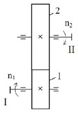
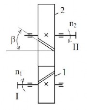
Figure 5-1 Gear transmission
straight tooth
Figure 5-2 Gear transmission
inclined dental implant
The working principle of the gear transmission can be summarized as follows: shaft I rotates with the number of revolutions n 1 , through the key joint to make gear 1 rotate. The teeth of gear 1 mesh with the teeth of gear 2, pushing the teeth of gear 2 to move, making gear 2 rotate, thanks to the key joint shaft II rotates with the number of revolutions n 2 .
Transmission of motion by meshing, so in the gear transmission there is almost no slippage (there is only the phenomenon of profile slippage at the top and root of the teeth), the transmission efficiency of the transmission is very high.
The gear tooth has a tooth crest, a tooth root, a tooth profile, and a transition curve between the tooth profile and the tooth root (Figure 5-5). During transmission, the opposing profile pairs contact each other on the meshing line.
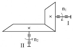
Figure 5-3 Bevel gear transmission
5.1.2. Classification of gear transmission
Depending on the shape of the gear, tooth direction and tooth profile, gear transmission is divided into the following types:
- Cylindrical gear transmission: gears are round rotating cylinders, with straight lines, often used to transmit motion between two parallel shafts, rotating in opposite directions. Cylindrical gear transmissions have the following types:
+ Straight tooth spur gear transmission, the direction of the teeth coincides with the generating line
of the cylindrical surface, schematic representation of the spur gear transmission on (Figure 5-1).
+ Helical gear transmission , the direction of the teeth is inclined compared to the generating line
of the cylindrical surface at an angle d, schematic representation of the upper helical gear transmission (Figure 5-2).
+ V-shaped bevel gear transmission, the gear is made up of two helical gears with the same tilt angle, opposite tilt directions, the diagram shows the V-shaped bevel gear transmission above ( Figure 5-6).
- Bevel gear transmission, also known as bevel gear transmission: gears have a truncated cone shape, often used to transmit motion between two perpendicular shafts. Bevel gear transmissions have the following types:
+ Straight bevel gear transmission: straight tooth path, coincident with the generating line
of the cone face.
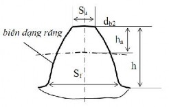
Figure 5-5 Gear teeth
Figure 5-4 External gear transmission
Figure 5-6 V-gear transmission
+ Helical bevel gear transmission: the tooth path is straight, inclined to the generator line of the cone surface.
+ Circular arc bevel gear transmission: the tooth path is a circular arc.
- Open-body gear transmission: the tooth profile is a segment of the open-body path of the circle. This is a commonly used transmission, most of the gear pairs encountered in practice are of this type.
- Novikov gear train: the tooth profile is a part of a circle.
- Cycloid gear transmission: the tooth profile is a segment of the cycloid path.
- Rack and pinion transmission: rack and pinion is a special gear with an infinite diameter, used to convert rotary motion into translational motion and vice versa .
- Planetary gear transmission: at least one gear in the transmission has a shaft
rotate around the center of another gear.
- Internal meshing gear transmission: the centers of the two gears are on the same side of the meshing center, the two rolling circles are in internal contact with each other.
- Wave gear transmission: the gear teeth have a continuous wave form, often using internal meshing to achieve a very large transmission ratio.
In this chapter, mainly presented open body gear transmission, meshing
Other types of transmissions will be covered in the gear monograph .
5.1.3. Geometric parameters of spur gear transmission
The shape and dimensions of the spur gear unit are determined
through the following main geometric parameters (Figures 5-4, 5-5, 5-7):
- Gear tooth module , symbol is m, unit of measurement is mm. Gears with the same module will mesh with each other. The value of module m is taken according to a standard number series, to limit the number of gear machining tools used in practice.
For example: 1; 1.25; (1.375); 1.5; (1.75); 2; (2.25); 2.5; 3; (3.5); 4; (4.5); 5; (5.5); 6;
(7); 8; (9); 10; (11); ..
- Tooth peak height coefficient h a - this coefficient determines whether the tooth is high or low.