- Suck fuel into high pressure chamber
During the suction phase, the piston moves up due to the spring force, increasing the volume of the high-pressure chamber. At this time, the solenoid valve of the injector pump does not operate. The solenoid valve needle is at the rightmost position (Figure 2-64), connecting the high-pressure chamber to the fuel supply line. Due to the pressure difference, fuel from the supply line is sucked into the high-pressure chamber.
(2)
(3)
(1)
(4)
(5)
(12)
(6)
(7)
(8)
(11)
(9)
(10)
Figure 2-65. Pre-spray phase
1. Injector cam; 2. Roller rocker arm; 3. Piston spring; 4. Pump piston; 5. Solenoid valve needle;
6. Injector pump solenoid valve; 7. Return fuel line; 8. Fuel supply line;; 9. Spring; 10. Injector; 11. Jet piston; 12. High pressure chamber
Pre-spray
The injector cam pushes the injector pump piston down through the roller rocker arm, causing some of the fuel in the high-pressure chamber to flow back to the feed line. At this time, the ECM will start the operating cycle, activating the solenoid to move the valve needle to press against the valve seat to close the passage between the feed line and the high-pressure chamber. As a result, the pressure in the high-pressure chamber increases. When the injector lift pressure (about 18,000 Kpa) is greater than the spring force, the injector will lift off its seat and start the pre-injection cycle.
- Limiting the injector stroke with hydraulic wedge
1
4
5
6
7
1
2
3
2
3
Figure 2-66. Hydraulic wedge forming process
1. Nozzle spring chamber; 2. Spring; 3. Nozzle body; 4. Unblocked stroke; 5. Leakage slot; 6. Hydraulic cushion; 7. Shock absorber piston.
(2)
(1)
(3)
(4)
(11
(5)
(6)
(7)
(10)
(8)
(9)
Figure 2-67. Main injection phase
1. Injector cam; 2. Roller rocker arm; 3. Piston spring; 4. Pump piston; 5. Injector pump solenoid valve; 6. Return fuel line; 7. Fuel supply line;; 8. Spring;
9. Injector; 10. Jet piston; 11. High pressure chamber
In the pre-injection phase, the injector stroke is controlled by a hydraulic wedge. Therefore, the pre-injection quantity can be precisely measured.
About 1/3 of the total stroke, the injector opens without being controlled, a pre-injection quantity is injected into the combustion chamber. As soon as the damper piston enters its cylinder in the injector chamber, the fuel above the injector can only enter the spring chamber through the leakage gap (between the damper piston and its cylinder), forming a hydraulic wedge that limits the injector's stroke in the pre-injection phase.
- End of pre-spray phase
The pre-injection phase ends immediately after the injector opens. Because the pump piston is still moving down, it increases the pressure in the high-pressure chamber and pushes the jet piston down, increasing the volume in the high-pressure chamber. This results in a decrease in pressure and closes the injector, ending the pre-injection phase.
(2)
(1)
(3)
(4)
(5)
(6)
(12)
(7)
(8)
(11)
(9)
(10
(2)
(3)
(1)
(4)
(5)
(6)
(7)
(8)
(9)
(10)
Figure 2-68. End of main injection phase
1. Injector cam; 2. Roller rocker arm; 3. Piston spring; 4. Pump piston; 5. Solenoid valve needle; 6. Injector pump solenoid valve; 7. Return fuel line; 8. Fuel supply line;; 9. Spring; 10. Injector needle; 11. Jet piston; 12. Valve needle
Main injection phase
The high-pressure chamber pressure increases again immediately after the injector closes because the solenoid valve remains closed and the pump piston continues to move down. When the fuel pressure increases (about 30,000 kPa) greater than the injector closing force corresponding to the previous injection stage, the injector rises from the base again and a main injection volume is injected into the engine cylinder.
End of main injection phase
When the ECM stops activating the injector pump electronics, the solenoid valve needle returns to its original position thanks to the return spring, connecting the high pressure chamber to the fuel supply line. The fuel in the high pressure chamber can return to the fuel supply line, causing the fuel pressure to decrease. The injector closes, ending the main injection phase.
Return of fuel injector pump
(1)
(2)
(5)
(3)
(4)
Figure 2-69. Fuel return diagram
1. Fuel leak 2. Pump piston; 3. Return fuel line;
4. Fuel supply line; 5. Zigzag.
The fuel return line in the injector pump has the following functions:
- Cool the injector pump by the fuel flow from the feed line through the injector pump and then return through the fuel return line.
- Discharge fuel leaking through the pump piston gap into the tank
- Separate the fuel vapor bubbles in the fuel supply line to the injector pump using the fuel vapor bubble separator on the fuel return line.
2.6. EFI-diesel UP system
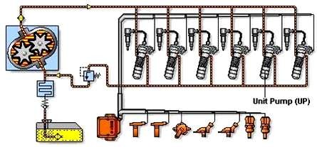
Figure 2-70. Overview of EFI-diesel UP
With the UP system, high pressure fuel is supplied by a single high pressure pump (1 single high pressure pump per cylinder). The fuel in the high pressure pump is compressed by the high pressure pump piston, the piston is driven by the engine camshaft. The compressed high pressure fuel is supplied to the injector through the high pressure pipes.
2.6.1. System diagram
Figure 2-71. EFI-diesel UP fuel system diagram
1. Intake manifold pressure sensor; 2. Injector; 3. Single high pressure pump
4. Electronic control unit (ECU); 5. Accelerator pedal position sensor; 6. Camshaft sensor; 7. Engine speed sensor; 8. Engine temperature sensor
The UP fuel system is controlled by the ECU. It receives signals from sensors such as accelerator pedal position, engine speed, engine temperature... to process and control the operation.
The operation of a single high pressure pump is shown in Figure 2-71.
The main parts of the system are shown in Figure 2-72.
(4)
(3)
(5)
(2)
(6)
(1)
(7)
(8)
Figure 2- 72. Components of the UP fuel system
1. Camshaft; 2. Single pump; 3. Return fuel line; 4. High pressure fuel line; 5. Injector; 6. Low pressure fuel supply; 7. Pipe
fuel; 8. Fuel supply line
2.6.2. Structure and operation of high pressure pump
1. Structure
The high pressure pump in the EFI-diesel UP fuel system has the following main components:
Figure 2-73. External shape of
UP high pressure pump
1. Cam; 2. Roller; 3. High pressure cylinder; 4. Suction chamber; 5. Valve body; 6. Injection pump head; 7. Injection pump solenoid; 8 High pressure chamber; 9. Pump piston; 10. Return spring; 11. High pressure pipe; 12. Injector
In addition, there is also a door on the pump body.
fuel in and out
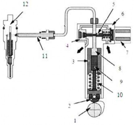
Figure 2-74. Basic components of the high pressure pump and UP nozzle
1. Cam; 2. Roller; 3. High pressure cylinder; 4. Suction chamber; 5. Valve body; 6. Injection pump head; 7. Injection pump solenoid; 8 High pressure chamber; 9. Pump piston; 10. Return spring; 11. High pressure pipe; 12. Injector
2. Activities
The single high pressure pump of the UP system is usually installed in the engine body. The camshaft supplying fuel drives the lifter through the roller. The return spring always presses the roller against the cam and the lifter acts on the piston, causing the piston to move up and down in the BCA body. Low pressure fuel flows through the intake port in the engine body and enters the compression chamber.
The solenoid valve spring always presses the solenoid valve needle on the stopper. When the solenoid valve is energized, the steel disc is sucked, pulling the valve needle to close the low pressure oil line, preventing it from communicating with the compression chamber. At that time, fuel is supplied to the injector through the high pressure connector and high pressure pipe.
The camshaft cam of the engine lifts the pump piston up through the roller lifter. The fuel injection process begins when the ECU provides an electrical control signal to the Solenoid valve, the Solenoid valve steel disc is sucked, causing the valve needle to close, preventing the compression chamber from communicating with the low pressure oil line. The fuel in the compression chamber is compressed and the fuel pressure in the high pressure pipe and injector increases. The injector starts to inject fuel into the combustion chamber when the fuel pressure is about 300 bar. During the fuel injection process
fuel , fuel pressure increases to about 1800 bar .
As soon as the ECU stops providing the control signal, the Solenoid valve opens and the spring pushes the valve needle against the stopper, opening the low pressure oil passage and the compression chamber. The oil pressure in the compression chamber and the injector drops suddenly, the injector closes and the fuel injection process ends.
The pump piston continues to move down, fuel is drawn into the compression chamber and a new injection process begins.
2.7. HEUI fuel system
2.7.1. Overview of HEUI fuel system
The HEUI (Hydraulically Actuated Electronically Controlled Unit Injector) fuel system is one of the major improvements of the Diesel engine. It is also a part of ACERT technology (ACERT technology is a new improvement based on the principle of building an engine
into clusters of details that work together to control the processes.
Figure 2-75. HEUI injector pump
engine performance. ACERT technology engines improve engine life, fuel efficiency and performance.
Cam Control - Injection speed depends on cam rotation speed - Injection timing: when the piston moves | |
Traditional NL system | |
Maybe you are interested!
-

 Basic Content of Vietnamese History Section in High School Program 2018
 -
 Basic Knowledge Content That Can Be Applied Storymap When Teaching About World Civilizations Of The General Education Program High School History Subject
 -
 Basic Hematological Indexes of Vietnamese High-Level Female Badminton Players and High-Level Female Athletes of Some Vietnamese Sports
 -
 Average Vmtt Thickness of High Blood Pressure and Normal Blood Pressure Groups
 -
 Some Factors Related to High Blood Pressure in People 18 - 69 Years Old
Orange
HEUI system
High pressure fuel to the injector
Electronic control
- Spray time
- Spray volume
Hydraulic oil pressure booster
- Injection pressure
- Spray speed
High pressure piston
Figure 2-65. Difference between HEUI system and conventional fuel system