working process | ||
3. The piston pin is scratched on the surface. | Lubricating oil has dirt and impurities. | - Rapid wear of parts. |
4. Piston pin is cracked. | Due to poor manufacturing quality, engine failure. | - Make the engine unable to operate. |
Maybe you are interested!
-

 Procedure for Applying Law in Criminal Investigation Cases
 -
 Provisions of Criminal Procedure Law on Depositing Money or Valuable Assets as Security
 -
 Administrative procedure reform in the Customs sector today - 9
 -
 Costing Procedure Using Sequential Transfer Method
 -
 Temporary Emergency Measures Under Vietnamese Civil Procedure Law
4.1.7 Piston rings
Damage
Reason | Consequence | |
1. Friction with cylinder wall, edge wear. | - Due to lack of lubrication. - The working stroke of the Piston has complex force. - Due to impact with the Piston groove. | - Causes air bubbles and oil leaks. - Reduce engine power. |
2. The top piston ring wears the most. | - Working under high pressure, high temperature and lack of lubrication. | - Increases the gap between the piston ring and the groove, causing oil to bubble, air leakage, and reducing engine power. |
3. Piston rings are stuck or broken. | - Due to high temperature, soot. - Lack of lubricant. | - Causes scratches on the cylinder. |
4.1.8 Connecting rod
Damage
Reason | Consequence | |
1. The connecting rod is bent. | Due to engine knocking, premature ignition, stuck piston, incorrect cam setting. | The bent TT causes the piston to deviate to one side, the piston and piston rings are tilted, reducing the tightness, the piston assembly, piston rings, and cylinder wear quickly. and uneven wear. |
2. TT bolts and nuts are loose or broken. | Due to fatigue, due to bending force, large tensile force, due to too much tightening force. | The engine does not work, causing damage to the parts. |
3. The connecting rod has a clogged oil hole. | Because the oil has a lot of dirt, because the bearing is rotated. | The oil hole is clogged, preventing oil from reaching the piston and cylinder, so it cannot lubricate these parts, leading to damage. broken parts are very dangerous. |
4. The connecting rod is twisted. | Due to sudden force due to the above reasons, the gap | The TT is twisted, causing the center lines of the large end hole TT and the small end TT to not be on the same plane. The piston rotates. |
between the connecting rod big end and the connecting rod neck oil is too large and the oval cone wear is large. | The cylinder bearing is deviated, the big end and small end wear out quickly. The big end and small end wear out quickly because the bearing rotates, causing the mounting gap to wear out quickly, causing collision and jamming. | |
5. Connecting rod is cracked or broken. | Due to the force being too great due to the above factors, the piston is stuck. stuck in cylinder | The engine loses its ability to work and causes damage to other engine parts. |
6. Large and small TT head holes are worn widely. | Due to impact (bearing gap is too large), due to wear (bearing is rotated). | The clearance between the bearing and the large and small end holes increases, the bearing rotates, blocking the oil hole, causing jamming and knocking. |
4.1.9 Connecting rod bearing - Bearing
Damage
Reason | Consequence | |
1. Silver is scratched. | - Due to dirty lubricating oil, grinding powder gets into the working surface of the bearing. | - Reduce main oil circuit pressure. |
2. Silver is pitted. | - Due to wear or lack of lubricating oil, oil quality is not guaranteed, Long-term overload, oil with too much abrasive powder, oil pressure too low. | - Reduces main oil circuit pressure, engine knocks, broken shaft, engine damage. |
3. Silver is sticky and peeled off. | - Due to lack of lubricating oil, if the oil pressure drops by 1KG, the gap will be Clearance between bearing and wear shaft 0.1 mm. | - Reduces main oil circuit pressure, engine knocks, broken shaft, engine damage. |
4.1.10 Connecting rod bolts.
Damage
Reason | Consequence | |
1. Increased bolt length | - Due to repeated disassembly and over tightening specified moment. | - Make self-removing bolts |
2. Reduced bolt diameter | - Due to multiple disassembly and assembly, tightening beyond the specified torque. | - Make self-removing bolts |
3. The bolt body is bent | - Due to multiple disassembly and assembly, tightening beyond the specified torque. | - Difficult to disassemble and assemble |
4.1.11 Crankshaft.
Damage
Reason | Consequence | |
1. The working surfaces of the shaft collars and flange collars are scratched. | Since oil contains a lot of dirt, if the scratch is deep it may be caused by sand or metal. | Causes the shaft bearings to wear quickly, wearing into the edge. |
2. The shaft neck and connecting rod positions have worn cones and ovals. | Due to friction between the bearing and the shaft neck. | Increase the assembly gap to create impact during the process. |
Lubricant quality | work. | |
poor, oil contains | Increase clearance between shaft collars | |
many impurities | and neck leading to pressure drop | |
Due to silver wear. | Lubricating oil capacity. | |
Due to the change in combustion air force | ||
cyclical | ||
Due to long working days. | ||
3. Silver working surface | Due to lack of lubricant, | Make the parts wear out |
burnt gray, pitted | poor lubrication | fast. |
oil contains many impurities | ||
matter. | ||
Due to the clearance between the bearing and the shaft | ||
too small | ||
Due to clogged oil line | ||
to the phenomenon of lack of lubrication | ||
slippery. | ||
4. The shaft is burned with the metal layer. | Due to the gap between the joints | Reduces shaft life |
type on work surface. | shaft and bushing too small. | elbow as well as silver. If |
Due to lack of lubrication, blockage | heavy can damage details | |
oil line or fault | of the crankshaft. | |
manufacturing. | ||
5. The shaft neck is bent or twisted. | Due to water getting in | Make the piston move |
combustion chamber, by detonation | skewer in cylinder. | |
or due to piston rod failure | Causes clutch wear and | |
transmit | Oval for cylinder, piston. | |
Due to long working days. | ||
Due to improper disassembly and assembly | ||
art | ||
6. Oil road | Because in the lubricating oil there is | Make the neck position, neck |
blocked | contain a lot of dirt. | The edge wears out quickly due to lack of |
Due to old oil lines | lubricant | |
not flushed | If there is a large lack of oil it can cause | |
burning phenomenon, silver bundle | ||
7. Shaft is cracked or broken. | Due to detonation phenomenon. | Damage the crankshaft. |
Due to piston rod failure | Engine failure. | |
transmission caused. | ||
Due to water ingress | ||
combustion chamber | ||
Due to the manufacturer's fault | ||
or by material | ||
not guaranteed | ||
Due to improper disassembly and assembly |
art |
4.1.12 Flywheel.
Damage
Reason | Consequence | |
1. Worn and chipped gears. | Working for a long time, due to the meshing gears of the starter and gears poor flywheel on start. | The starter makes a noise, damaging the flywheel ring gear and starter ring gear when working. |
2. Surface is scratched and pitted. | Due to clutch slippage. Due to metal filings entering the work surface. Due to the raised rivet. | Scratch the working surface of the flywheel. Causes clutch slippage during operation. |
3. The flywheel is cracked. | Made of material. | Dangerous to people and engines. |
4. The flywheel is stiff. | Due to high temperature during working or due to the phenomenon of clutch | Make the flywheel and clutch slip when working. |
5. Flywheel is warped. | Due to improper assembly according to technical requirements. | Causes vibration while working and does not work smoothly. |
6.Flywheel surface is unevenly worn. | Due to improper assembly according to technical requirements. Due to flywheel warping. | Causes vibration when working and does not work smoothly, reducing engine power. |
4.1.13 Batteries and battery covers.
Battery - Battery bearings wear out quickly mainly due to impact loads, the diameter of the bearing is oval, increasing the clearance between the bearing and the battery.
a. Battery :
- During operation, 3 positions are often worn: The position in contact with the piston pin hole and the battery bushing.
b. Silver battery:
- The bearing is fitted with a glove to the small end of the connecting rod and is loosely fitted with the piston pin, and is worn during operation.
4.2 Disassembly, assembly, inspection.
4.2.1 Procedure for removing and installing the engine cover (Toyota 1NZ-FE engine)
a. Disassembly process:
* Preparation work before disassembly:
- Clean the outside of the machine and around the disassembly area.
- Prepare tools for disassembly and parts storage.
- Support the engine firmly before removing.
- Remove the parts mounted on the machine surface: spark plugs, injectors, wires, high voltage wires...
- When removing the suction and discharge assembly, pay attention to disassembling according to the correct technical process.
* Machine face removal process:
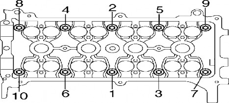
- Use a wrench and connecting hand to remove the bolts from both ends to the middle, cross each other, alternately loosen and do this several times before removing completely.
- Take the machine out.
Note : Do not remove the machine cover while the engine is still hot.
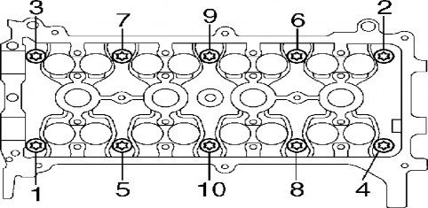
Figure 2.16. Order of removing machine face bolts and nuts .
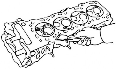
b. Detailed cleaning:
- Clean the machine surface.
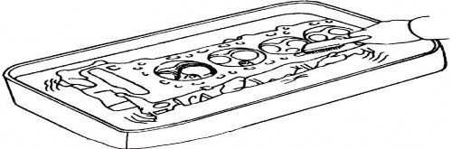
- Clean the combustion chamber.
- Clean the guide tube.
- Clean up any debris from the mattress and any glue remaining on the surface.
c. Check:
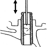
* Check for cracks:
For large cracks, observe with the naked eye. For small cracks, check as follows:
+ Method 1: Check with paint.
+ Method 2: Use lubricant and colored powder to check.
* Check threaded joints : Observe by eye or use its bolt to
try.
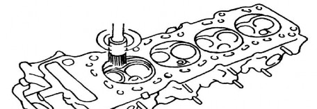
* Check the warping of the assembly surfaces on the machine:
Method 1: Use a level and feeler gauge to check the warping of the assembled surfaces.
Method 2: Use colored powder and a map to check.
Depending on the type of engine, the allowable warpage value for each type is different.
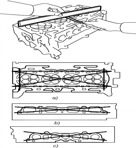
Table of parameters for maximum allowable warpage of mounting surfaces of some engines (unit: mm).
TT
Engine type | Machine cover mounting surface | Suction tube assembly mounting surface | Exhaust pipe mounting surface |
1
1NZ-FE; 4A-F | 0.05 | 0.1 | 0.1 | |
2 | 2AZ-FE | 0.05 | 0.08 | 0.08 |
3 | 4A-GE | 0.05 | 0.05 | 0.1 |
2GR-FE | 0.1 | 0.1 | 0.1 |
d. Machine face assembly process:
*Preparation work before installation:
- Clean the machine cover before installation.
- Use a dry cloth to wipe or spray the machine surface dry with compressed air.
- Apply a little lubricant to each cylinder.
- Apply a thin layer of grease to the machine face pad.
* Machine face installation process:
- Place the faceplate on.
- Place the machine face in.
- Install the washers and bolts by hand first.
- When tightening, tighten according to the rule from the middle to the two ends, cross each other and tighten alternately many times before tightening to the correct specified force.
- Use the torque wrench to tighten the bolts to the correct torque specified for the bolts. Tightening torque 29 Nm (300kg.cm).
After tightening to the specified force, this type of engine requires further tightening.
Refer to the torque values for the face bolts of some engines:
Engine type
Torque | Additional tightening rules | |
2A-Z | 70 Nm (714 kg.cm) | A 90 0 angle |
4A-F | 60 Nm (610 kg.cm) | |
4A-GE | 29 Nm (300 kg.cm) | Tighten two more times, each time tightening an additional 90 0 angle . |