Convention for describing line shapes in linetype.
The line type starts with the letter A. This letter A specifies that the object ends with a solid line.
Positive values specify the length of the solid line.
Negative values specify the length of the gap.
Number 0 specifies a line segment with length 0 or a dot.
Thus, the line shape described in the sample1.lin file above has the following form:
Note: The A (alignment) code specifies how to draw line shapes at the end points of drawing objects. The Alignment code is automatically included in the .LIN file definition.
Normal form.
Shortened form.
Long lasting.
The form is too short (turns the object into a solid line).
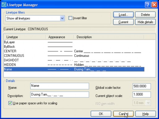
2.2. Create linetype by editing directly in .LIN
Each line type in the .LIN file is described in two lines:
*linetype_name,description A,descriptor1,descriptor2, ...
The * before the line type name is required.
Linetypename : The name of the line, which will appear in the linetype manager.
Description: The description string may or may not be present and must not exceed 47 characters in length.
A: specifies the end of the drawn object with a solid line.
Descriptor 1,2,.. : Byte describing the line type (as described above).
IV. Complex path containing shape object
The way to describe dashes, spaces and dots is similar to that in the simple line description file. The syntax to describe a line is the same as that of a simple line. For a line that contains a shape object, we just need to add a shape description syntax to the line description as follows:
[shapename,shxfilename] or [shapename,shxfilename,transform]
Shape name: The name of the shape drawing object. If the object name is not in the shape file, AutoCAD will assume that there is no description of the shape object in the line drawing.
Shxfilename : The name of the .shx file containing the shape object to be inserted into the line. The name and path must be specified, otherwise AutoCAD will search in the default folder containing .SHX files: Documents and Settings[user name]Application DataAutodeskAutoCAD 2005R16.0enuSupport.
Transform: This is an optional item, including parameters corresponding to the transformation when inserting shape and line objects. The value of transform is described in the table below, each parameter is separated by a comma.
The values of the Transform parameters.
Meaning Value
R=## Relative rotation
A=## Absolute rotation
The relative rotation angle of the shape to the drawn line.
Absolute rotation angle relative to the OX axis of the WCS coordinate system.
For example :
S=## Scale Scale factor (of the inserted shape to the shape described in the shape file).
X=## X offset Linear displacement (X units)
Y=## Y offset Displacement perpendicular to the line
straight. (Y units). (X,Y can be negative numbers)
Use the load command to load the ltypeshx.shx file into the drawing, then type the Shape command to insert a shape named bat into the drawing. The shape of bat appears as follows:
Open the LT_Sample.LIN file and type the following 3 linetypes:
*BAT1LINE, --- [BAT1] --- [BAT1] --- [BAT1]
A,38.1,-38.1,[BAT,ltypeshp.shx,S=5],-12.7
*BAT2LINE, --- [BAT2] --- [BAT2] --- [BAT2]
A,38.1,-38.1,[BAT,ltypeshp.shx,S=5,R=0,X=-20.0],-12.7
*BAT3LiNE, --- [BAT3] --- [BAT3] --- [BAT3]
A,38.1,-38.1,[BAT,”C:sampleltypeshp.shx”,S=5,y=-6.0,r=90,X=-6],-12.7 The shapes of the above linetypes appear in the following order:


Note: linetype names do not have to be uppercase. The order of transforms does not have to be fixed.
1. Complex path containing text object.
The syntax for describing text objects in complex line shapes is as follows: (* note that in AutoCAD 2005, the syntax for creating line shapes containing characters is different from previous versions, it requires more stringent requirements than previous versions).
["text",textstylename,scale,rotation,xoffset,yoffset]
Text: the character string to be inserted.
Style: The name of the font style that AutoCAD will use to format the text.
Scale,rotation,xoffset,yoffset : Similar to the above transform parameters.
For example :
*HOT_WATER_SUPPLY1,---- HW ---- HW ---- HW ---- HW ---- HW ----
A,.5,-.2,["HW",STANDARD,S=.1,R=0.0,X=-0.1,Y=-.05],-.2
The result is in the form of a line as follows:
Note: If s=0 then the text will be taken according to the font and have a font size (height) of 1.
V. Create cross-sectional templates.
1. Section template file.
The section pattern is described by AutoCAD in a file with a division.
open banner
g .PAT. We can use
use
Available cross sections are described in the
ACAD.PAT and ACADISO.PAT files or
on one's own
create
The individual templates are saved in .PAT files in ACII file format. Note,
other
with
spread
line, cross section
Section file can only contain one section type and file name must be
same name
By default *.pat is saved in the Documents and Settings[user
name]Application DataAutodeskAutoCAD 2005R16.0enuSupport.
After creating the section types in individual files. You can copy the section descriptions in these files into the Acad.Pat or AcadIso.Pat files, to add them to the Patern field in the BHatch command.
Similar to line shapes, we divide cross-section shapes into two types: Simple cross-section shapes and complex cross-section shapes.
A simple cross-sectional pattern is a pattern that contains only a straight line.
A complex cross-sectional pattern is a pattern consisting of many families of straight lines.
2. Create a simple cross section.
A cross-section pattern in a .PAT file is described as follows:
g more
g next to each other. Syntax description
*pattern-name[, description]
angle, x-origin,y-origin, delta-x,delta-y [, dash1, dash2, ...]
Pattern – name : The cross-section name will be descriptive and cannot contain spaces.
Description: Description (Optional) and must not exceed 80 characters
Angle: Angle of the cutting line.
x-origin : The x-coordinate of the point
standard
g to draw the cross section. Usually we
use origin point with coordinates (0,0)
y-origin : Coordinate of the reference point
dun
g as root
coordinates
delta-x : Displacement of the cutting line in the vertical direction.
delta-y : Displacement of the cutting line perpendicular to the vertical direction.
dash1, dash2, ... : Only used when the cuts are discontinuous lines.
For example
The
This value describes the line type (including dashes and fills).
g).
I
file named L123.PAT
content as follows
*L123, proposed future trailers 0, 0.0, 0.0.5
Maybe you are interested!
-

 Car body electrical practice - 8
zt2i3t4l5ee
zt2a3gs
zt2a3ge
zc2o3n4t5e6n7ts
If the voltage is out of specification, replace the wire or connector.
If the voltage is within specification, install the front fog light relay and follow step 5.
Step 5 Check the front fog light switch
- Remove the D4 connector of the fog light switch
- Use a multimeter to measure the resistance of the front fog light switch.
Measurement location
Condition
Standard
D4-3 (BFG) -D4-4 (LFG)
Light switchFront Fog OFF
>10kΩ
D4-3 (BFG) -D4-4 (LFG)
Front fog light switchON
<1 Ω
- Standard resistor
D4 connector is located on the combination switch assembly.
If the resistance is out of specification, replace the combination switch (the fog light switch is located in the combination switch).
If the resistance is within specification, follow step 6.
Step 6 Check wiring and connectors (front fog light relay-light selector switch)
- Disconnect connector D4 of the combination switch assembly
- Use a voltmeter to measure the voltage value of jack D4 on the wire side.
Measurement location
Control modecontrol
Standard
D4-3 (BFG) - (-) AQ
TAIL
11 to 14 V
D4 connector for the wiring of the combination switch assembly
If the voltage does not meet the standard, replace the wire or connector.
If the voltage is within standard, there may have been an error in the previous measurements.
Step 7 Check the front fog lights
- Remove the front fog light electrical connector.
- Supply battery voltage to the fog lamp terminals
Jack 8, B9 of front fog lamp on the electrical side
blind first.
Power supply location
Terms and Conditions
Battery positive terminal - Terminal 2Battery negative terminal - Terminal 1
Fog lightsbefore morning
- If the light does not come on, replace the bulb.
If the light is on, re-plug the jack and continue to step 8.
Step 8 Check wiring and connectors (relay and front fog lights)
- Disconnect the B8 and B9 connectors of the front fog lights.
- Use a voltmeter to measure voltage at the following locations:
Measurement location
Switch location
Terms and Conditions
B8-2 - (-) AQ
Electric lock ON TAIL size switchFog switch ON
11 to 14 V
B9-2 - (-) AQ
Electric lock ONTAIL size switch Fog switch ON
11 to 14 V
B8 and B9 connectors on the front fog lamp wiring side
Voltage is not up to standard, repair or replace the jack. If up to standard, there may have been an error in the measurement process.
2.2.4. Procedure for removing, installing and adjusting fog lights 1. Procedure for removing
- Remove the front inner ear pads
Use a screwdriver to remove the 3 screws and remove the front part of the front inner ear liner
-Remove the fog light assembly
+ Disconnect the connector.
+ Use a screwdriver to remove 3 screws to remove the fog light cover
2. Installation sequence
-Rotate the fog lamp bulb in the direction indicated by the arrow as shown in the figure and remove the fog lamp from the fog lamp assembly.
-Rotate the fog light bulb in the direction indicated by the arrow as shown in the figure and install the light into the fog light assembly.
- Use a screwdriver to install the fog light cover
-Install the electrical connector
Attention: Be careful not to damage the plastic thread on the lamp assembly.
- Install the front inner ear pads
Use a screwdriver to install the front inner bumper with 3 screws.
3. Prepare the vehicle to adjust the fog light convergence. Prepare the vehicle:
- Make sure there is no damage or deformation to the vehicle body around the fog lights.
- Add fuel to the fuel tank
- Add oil to standard level.
- Add engine coolant to standard level.
- Inflate the tire to standard pressure.
- Place spare tire, tools and jack in original design position
- Do not leave any load in the luggage compartment.
- Let a person weighing about 75 kg sit in the driver's seat.
4. Prepare to check the fog light convergence
a/ Prepare the vehicle status as follows:
- Place the car in a dark enough place to see the lines. The lines are the dividing line, below which the light from the fog lights can be seen but above which it cannot.
- Place the car perpendicular to the wall.
- Keep a distance of 7.62 m between the center of the fog lamp and the wall.
- Park the car on level ground.
- Press the car down a few times to stabilize the suspension.
Note: A distance of approximately 7.62 m is required between the vehicle (fog lamp center) and the wall to adjust the convergence correctly. If the distance of 7.62 m cannot be achieved, set the correct distance of 3 m to check and adjust the fog lamp convergence. (Since the target area varies with the distance, please follow the instructions as shown in the figure.)
b/ Prepare a piece of thick white paper about 2 m high and 4 m wide to use as a screen.
c/ Draw a vertical line through the center of the screen (line V).
d/ Set the screen as shown in the picture. Note:
- Keep the screen perpendicular to the ground.
- Align the V line on the screen with the center of the vehicle.
e/Draw the reference lines (H, V LH and V RH lines) on the screen as shown in the figure.HINT:
Mark the center of the fog lamp on the screen. If the center mark cannot be seen on the fog lamp, use the center of the fog lamp or the manufacturer's name mark on the fog lamp as the center mark.
H line (fog light height):
Draw a line across the screen so that it passes through the center mark. Line H should be at the same height as the center mark of the fog light bulb.
Line V LH, V RH (center mark position of left fog lamp LH and right fog lamp RH):
Draw two lines so that they intersect line H at the center marks.
5. Check the fog light convergence
a/ Cover the fog lamp or remove the connector of the other side fog lamp to prevent light from the unchecked fog lamp from affecting the fog lamp convergence test.
b/ Start the engine.
c/ Turn on the fog lights and make sure that the dividing line is outside the standard area as shown in the drawing.
6. Adjust the fog light convergence
Use a screwdriver to adjust the fog light to the standard area by turning the toe adjustment screw.
Note: If the screw is adjusted too far, loosen it and then tighten it again, so that the last rotation of the light adjustment screw is clockwise.
3. Self-study questions
1. Describe the operating principle of the lighting system with automatic headlight function
2. Describe the operating principle of the lighting system with the function of rotating headlights when turning
3. Draw diagram and connect lighting system on Hyundai Porter car
4. Draw diagram and connect lighting system on Honda Accord 1992
5. Draw the lighting circuit on a 1993 Toyota Lexus
LESSON 3 MAINTENANCE AND REPAIR OF SIGNAL SYSTEM
I. IMPLEMENTATION GOAL
After completing this lesson, students will be able to:
- Distinguish between types of signals on cars
- Correctly describe common symptoms and suspected areas causing damage.
- Connecting signal circuits ensures technical requirements
- Disassemble, install, check, maintain and repair the signal system to ensure technical requirements.
- Ensure safety in work and industrial hygiene
II. LESSON CONTENT
1. General description
The signal system equipped on cars aims to create signals to notify other vehicles participating in traffic about the vehicle's operating status such as: stopping, parking, braking, reversing, turning...
Signals are used either by light such as headlamps, brake lights, turn signals….. or by sound such as horns, reverse music….
Just like the lighting system. A signal system circuit usually consists of: battery, fuse, wire, relay, electrical load and control switch. Only some switches of the signal system are on the combination switch. The switches of other signals are usually located in different locations such as in the gearbox or brake pedal……
2. Maintenance and repair
2.1. Turn signals and hazard lights
The installation location of the turn signal is shown in Figure 3.1. The turn signal control switch is located in the combination switch under the steering wheel. Turning this switch to the right or left will make the turn signal turn right or left.
The hazard light switch is used when the vehicle has a problem while participating in traffic. When the hazard light switch is turned on, all the turn signals on the vehicle will light up at a certain frequency. The hazard light switch is usually placed separately from the turn signal switch (some old cars integrate the hazard and turn signal switches on the same combination switch cluster).
Figure 3.1 Turn signal switch Figure 3.2 Hazard switch
The part that generates the flashing frequency for the lights is called a turn signal relay. The turn signal relay usually has 3 terminals: B (positive power supply); E (negative power supply); L (providing the turn signal switch to distribute to the
lamp)
2.1.1. Circuit diagram
To generate the frequency for the turn signal, a turn signal relay is used in the turn signal circuit. The current from the turn signal relay will be sent to the turn signal switch assembly to distribute the current to the turn signal lights for the driver's purpose.
Figure 3.3. Schematic diagram of a turn signal circuit without a hazard switch
1. Battery; 2. Electric lock; 3. Turn signal relay; 4. Turn signal switch; 5. Turn signal lamp; 6. Turn signal lamp; 7. Hazard switch
Figure 3.4 Schematic diagram of turn signal circuit with hazard switch
1. Battery; 2. Combination switch cluster; 3. Turn signal;
4. Turn signal light; 5. Turn signal relay
Today's cars no longer use three-pin turn signal relays (B, L, E) but use eight-pin turn signal relays (figure 3.5) (pin number 8 is used for hazard lights).
For this type, the current supplying the turn signal lights is supplied directly from the turn signal relay to the lights.
div.maincontent .p { color: black; font-family:"Times New Roman", serif; font-style: normal; font-weight: normal; text-decoration: none; font-size: 14pt; margin:0pt; } div.maincontent p { color: black; font-family:"Times New Roman", serif; font-style: normal; font-weight: normal; text-decoration: none; font-size: 14pt; margin:0pt; } div.maincontent .s1 { color: black; font-family:"Times New Roman", serif; font-style: normal; font-weight: normal; text-decoration: none; font-size: 13pt; } div.maincontent .s2 { color: black; font-family:"Times New Roman", serif; font-style: italic; font-weight: normal; text-decoration: none; font-size: 14pt; } div.maincontent .s3 { color: black; font-family:"Times New Roman", serif; font-style: normal; font-weight: normal; text-decoration: none; font-size: 14pt; } div.maincontent .s4 { color: black; font-family:"Times New Roman", serif; font-style: normal; font-weight: normal; text-decoration: none; font-size: 13pt; } div.maincontent .s5 { color: black; font-family:"Times New Roman", serif; font-style: normal; font-weight: normal; text-decoration: none; font-size: 13pt; vertical-align: 1pt; } div.maincontent .s6 { color: black; font-family:"Times New Roman", serif; font-style: normal; font-weight: normal; text-decoration: none; font-size: 11pt; } div.maincontent .s7 { color: black; font-family:"Times New Roman", serif; font-style: normal; font-weight: normal; text-decoration: none; font-size: 14pt; vertical-align: -9pt; } div.maincontent .s8 { color: black; font-family:"Times New Roman", serif; font-style: normal; font-weight: normal; text-decoration: none; font-size: 11pt; } div.maincontent .s9 { color: #008000; font-family:"Times New Roman", serif; font-style: normal; font-weight: normal; text-decoration: none; font-size: 14pt; } div.maincontent .s10 { color: black; font-family:"Times New Roman", serif; font-style: italic; font-weight: normal; te
Car body electrical practice - 8
zt2i3t4l5ee
zt2a3gs
zt2a3ge
zc2o3n4t5e6n7ts
If the voltage is out of specification, replace the wire or connector.
If the voltage is within specification, install the front fog light relay and follow step 5.
Step 5 Check the front fog light switch
- Remove the D4 connector of the fog light switch
- Use a multimeter to measure the resistance of the front fog light switch.
Measurement location
Condition
Standard
D4-3 (BFG) -D4-4 (LFG)
Light switchFront Fog OFF
>10kΩ
D4-3 (BFG) -D4-4 (LFG)
Front fog light switchON
<1 Ω
- Standard resistor
D4 connector is located on the combination switch assembly.
If the resistance is out of specification, replace the combination switch (the fog light switch is located in the combination switch).
If the resistance is within specification, follow step 6.
Step 6 Check wiring and connectors (front fog light relay-light selector switch)
- Disconnect connector D4 of the combination switch assembly
- Use a voltmeter to measure the voltage value of jack D4 on the wire side.
Measurement location
Control modecontrol
Standard
D4-3 (BFG) - (-) AQ
TAIL
11 to 14 V
D4 connector for the wiring of the combination switch assembly
If the voltage does not meet the standard, replace the wire or connector.
If the voltage is within standard, there may have been an error in the previous measurements.
Step 7 Check the front fog lights
- Remove the front fog light electrical connector.
- Supply battery voltage to the fog lamp terminals
Jack 8, B9 of front fog lamp on the electrical side
blind first.
Power supply location
Terms and Conditions
Battery positive terminal - Terminal 2Battery negative terminal - Terminal 1
Fog lightsbefore morning
- If the light does not come on, replace the bulb.
If the light is on, re-plug the jack and continue to step 8.
Step 8 Check wiring and connectors (relay and front fog lights)
- Disconnect the B8 and B9 connectors of the front fog lights.
- Use a voltmeter to measure voltage at the following locations:
Measurement location
Switch location
Terms and Conditions
B8-2 - (-) AQ
Electric lock ON TAIL size switchFog switch ON
11 to 14 V
B9-2 - (-) AQ
Electric lock ONTAIL size switch Fog switch ON
11 to 14 V
B8 and B9 connectors on the front fog lamp wiring side
Voltage is not up to standard, repair or replace the jack. If up to standard, there may have been an error in the measurement process.
2.2.4. Procedure for removing, installing and adjusting fog lights 1. Procedure for removing
- Remove the front inner ear pads
Use a screwdriver to remove the 3 screws and remove the front part of the front inner ear liner
-Remove the fog light assembly
+ Disconnect the connector.
+ Use a screwdriver to remove 3 screws to remove the fog light cover
2. Installation sequence
-Rotate the fog lamp bulb in the direction indicated by the arrow as shown in the figure and remove the fog lamp from the fog lamp assembly.
-Rotate the fog light bulb in the direction indicated by the arrow as shown in the figure and install the light into the fog light assembly.
- Use a screwdriver to install the fog light cover
-Install the electrical connector
Attention: Be careful not to damage the plastic thread on the lamp assembly.
- Install the front inner ear pads
Use a screwdriver to install the front inner bumper with 3 screws.
3. Prepare the vehicle to adjust the fog light convergence. Prepare the vehicle:
- Make sure there is no damage or deformation to the vehicle body around the fog lights.
- Add fuel to the fuel tank
- Add oil to standard level.
- Add engine coolant to standard level.
- Inflate the tire to standard pressure.
- Place spare tire, tools and jack in original design position
- Do not leave any load in the luggage compartment.
- Let a person weighing about 75 kg sit in the driver's seat.
4. Prepare to check the fog light convergence
a/ Prepare the vehicle status as follows:
- Place the car in a dark enough place to see the lines. The lines are the dividing line, below which the light from the fog lights can be seen but above which it cannot.
- Place the car perpendicular to the wall.
- Keep a distance of 7.62 m between the center of the fog lamp and the wall.
- Park the car on level ground.
- Press the car down a few times to stabilize the suspension.
Note: A distance of approximately 7.62 m is required between the vehicle (fog lamp center) and the wall to adjust the convergence correctly. If the distance of 7.62 m cannot be achieved, set the correct distance of 3 m to check and adjust the fog lamp convergence. (Since the target area varies with the distance, please follow the instructions as shown in the figure.)
b/ Prepare a piece of thick white paper about 2 m high and 4 m wide to use as a screen.
c/ Draw a vertical line through the center of the screen (line V).
d/ Set the screen as shown in the picture. Note:
- Keep the screen perpendicular to the ground.
- Align the V line on the screen with the center of the vehicle.
e/Draw the reference lines (H, V LH and V RH lines) on the screen as shown in the figure.HINT:
Mark the center of the fog lamp on the screen. If the center mark cannot be seen on the fog lamp, use the center of the fog lamp or the manufacturer's name mark on the fog lamp as the center mark.
H line (fog light height):
Draw a line across the screen so that it passes through the center mark. Line H should be at the same height as the center mark of the fog light bulb.
Line V LH, V RH (center mark position of left fog lamp LH and right fog lamp RH):
Draw two lines so that they intersect line H at the center marks.
5. Check the fog light convergence
a/ Cover the fog lamp or remove the connector of the other side fog lamp to prevent light from the unchecked fog lamp from affecting the fog lamp convergence test.
b/ Start the engine.
c/ Turn on the fog lights and make sure that the dividing line is outside the standard area as shown in the drawing.
6. Adjust the fog light convergence
Use a screwdriver to adjust the fog light to the standard area by turning the toe adjustment screw.
Note: If the screw is adjusted too far, loosen it and then tighten it again, so that the last rotation of the light adjustment screw is clockwise.
3. Self-study questions
1. Describe the operating principle of the lighting system with automatic headlight function
2. Describe the operating principle of the lighting system with the function of rotating headlights when turning
3. Draw diagram and connect lighting system on Hyundai Porter car
4. Draw diagram and connect lighting system on Honda Accord 1992
5. Draw the lighting circuit on a 1993 Toyota Lexus
LESSON 3 MAINTENANCE AND REPAIR OF SIGNAL SYSTEM
I. IMPLEMENTATION GOAL
After completing this lesson, students will be able to:
- Distinguish between types of signals on cars
- Correctly describe common symptoms and suspected areas causing damage.
- Connecting signal circuits ensures technical requirements
- Disassemble, install, check, maintain and repair the signal system to ensure technical requirements.
- Ensure safety in work and industrial hygiene
II. LESSON CONTENT
1. General description
The signal system equipped on cars aims to create signals to notify other vehicles participating in traffic about the vehicle's operating status such as: stopping, parking, braking, reversing, turning...
Signals are used either by light such as headlamps, brake lights, turn signals….. or by sound such as horns, reverse music….
Just like the lighting system. A signal system circuit usually consists of: battery, fuse, wire, relay, electrical load and control switch. Only some switches of the signal system are on the combination switch. The switches of other signals are usually located in different locations such as in the gearbox or brake pedal……
2. Maintenance and repair
2.1. Turn signals and hazard lights
The installation location of the turn signal is shown in Figure 3.1. The turn signal control switch is located in the combination switch under the steering wheel. Turning this switch to the right or left will make the turn signal turn right or left.
The hazard light switch is used when the vehicle has a problem while participating in traffic. When the hazard light switch is turned on, all the turn signals on the vehicle will light up at a certain frequency. The hazard light switch is usually placed separately from the turn signal switch (some old cars integrate the hazard and turn signal switches on the same combination switch cluster).
Figure 3.1 Turn signal switch Figure 3.2 Hazard switch
The part that generates the flashing frequency for the lights is called a turn signal relay. The turn signal relay usually has 3 terminals: B (positive power supply); E (negative power supply); L (providing the turn signal switch to distribute to the
lamp)
2.1.1. Circuit diagram
To generate the frequency for the turn signal, a turn signal relay is used in the turn signal circuit. The current from the turn signal relay will be sent to the turn signal switch assembly to distribute the current to the turn signal lights for the driver's purpose.
Figure 3.3. Schematic diagram of a turn signal circuit without a hazard switch
1. Battery; 2. Electric lock; 3. Turn signal relay; 4. Turn signal switch; 5. Turn signal lamp; 6. Turn signal lamp; 7. Hazard switch
Figure 3.4 Schematic diagram of turn signal circuit with hazard switch
1. Battery; 2. Combination switch cluster; 3. Turn signal;
4. Turn signal light; 5. Turn signal relay
Today's cars no longer use three-pin turn signal relays (B, L, E) but use eight-pin turn signal relays (figure 3.5) (pin number 8 is used for hazard lights).
For this type, the current supplying the turn signal lights is supplied directly from the turn signal relay to the lights.
div.maincontent .p { color: black; font-family:"Times New Roman", serif; font-style: normal; font-weight: normal; text-decoration: none; font-size: 14pt; margin:0pt; } div.maincontent p { color: black; font-family:"Times New Roman", serif; font-style: normal; font-weight: normal; text-decoration: none; font-size: 14pt; margin:0pt; } div.maincontent .s1 { color: black; font-family:"Times New Roman", serif; font-style: normal; font-weight: normal; text-decoration: none; font-size: 13pt; } div.maincontent .s2 { color: black; font-family:"Times New Roman", serif; font-style: italic; font-weight: normal; text-decoration: none; font-size: 14pt; } div.maincontent .s3 { color: black; font-family:"Times New Roman", serif; font-style: normal; font-weight: normal; text-decoration: none; font-size: 14pt; } div.maincontent .s4 { color: black; font-family:"Times New Roman", serif; font-style: normal; font-weight: normal; text-decoration: none; font-size: 13pt; } div.maincontent .s5 { color: black; font-family:"Times New Roman", serif; font-style: normal; font-weight: normal; text-decoration: none; font-size: 13pt; vertical-align: 1pt; } div.maincontent .s6 { color: black; font-family:"Times New Roman", serif; font-style: normal; font-weight: normal; text-decoration: none; font-size: 11pt; } div.maincontent .s7 { color: black; font-family:"Times New Roman", serif; font-style: normal; font-weight: normal; text-decoration: none; font-size: 14pt; vertical-align: -9pt; } div.maincontent .s8 { color: black; font-family:"Times New Roman", serif; font-style: normal; font-weight: normal; text-decoration: none; font-size: 11pt; } div.maincontent .s9 { color: #008000; font-family:"Times New Roman", serif; font-style: normal; font-weight: normal; text-decoration: none; font-size: 14pt; } div.maincontent .s10 { color: black; font-family:"Times New Roman", serif; font-style: italic; font-weight: normal; te -
 Solution 2: Manufacturing Enterprises Must Regularly Maintain Transaction Activities With Partners To Increase Proficiency, Create
 -
 Investor Directly Manages Project Implementation
 -
 Create a Table of Area and Dimensions of Constructions.
 -
 Text editing - Lao Cai Community College - 8
I
file named L124.PAT
content as follows
*L124, proposed future trailers 90, 0.0, 0.1
*L125, proposed future trailers 0,1,0,1,2,-3,1
3. Create complex cross-section patterns.
Complex cross-sections are created from several different line families. These line families are described on a line and combined into a complex cross-section.
For example :
Doan
description after me
out one
cross section as shown
h ve
*lightning, interwoven lightning 90, 0.0, 0.5, .5,–.25
*lightning, interwoven lightning 0, –.25,.5, 0,.75, .25,–.25
*lightning, interwoven lightning 90, –.25,.5, 0,.5, .5,–.25
And the following code describes a complex cross section created by the above three families of lines:
*lightning, interwoven lightning
90, 0.0, 0..5, .5,–.25
0, –.25,.5, 0,.75, .25,–.25
90, –.25,.5, 0,.5, .5,–.25
VI. Menu.
1. Menu and menu files.
1.1. Menu types
There are a total of 10 menu types.
Pulldown menus: are dropdown menus such as file, edit,...
Context menus (shortcut menus): are menus that appear when you right-click on a location on the drawing.
Toolbars. Everyone knows this.
Image menus
Image menu: is the menu that appears as
when we enter the section
DrawSurfaces3d surfaces.
Screen menu: this menu appears when we go to Tools optionDisplayWindow elementDisplay screen menu.
Mouse device menus (Auxiliary menu): this menu is mouse devices such as pressing ctrl+left mouse, ctrl+right mouse.
Other devices of the input system (Button menu): this is the menu serving other devices of the input system such as electronic pens.
Digitizing input tables (tablets): a menu dedicated to cad digitizing tables. I also saw this for the first time at the IT exhibition last November (also known as digital tablets).
Helpstrings in status: Everyone knows this. When we move the cursor to the drop-down menus, helpstrings will appear in the status bar.
Hotkeys. For example ctrl+oOpen, etc…
1.2. Menu file types
We have the following types of menu files:
*.mnu
Sample menu file, this is an ACII code file that you can edit directly on it. | |
*.mns | This is the source menu file generated by AutoCAD based on the file. *.mnu. The structure of this file is a little simpler than mnu but basically the same. You can also edit directly on this file. When you change shortcuts, or change toolbars, ... right in CAD, CAD will record that change on this file. Not write to *.mnu file. CAD will not interfere with *.mnu file because it considers this file as a user-created file. |
*.mnc | Is the AutoCAD binary code compilation file. AutoCAD will compile |
Translate the above mns file into mnc file so that the computer can download and process it faster. | |
*.mnr | Binary file containing bitmap images used for image menus. |
*.mnl | The acci file contains the Autolisp programs that come with the menu. It will be loaded automatically if it has the same name as the *.mnc file. |
The above files form a family of menu files.
When a menu file is loaded, it is registered in the registry and the next time AutoCAD starts it will reload this menu file.
The process of loading a menu is as follows:
Begin
Convention
+ : Found
-- : Not found
+
+
Find *.mns Find *.mnc
-- --
Find *.mnc
--
+
Find *.mnu
--
+
End
Create file
*.mnc and *.mnr are based on *mns files.
Translate *.mnu to *.mns and *.mnc
create *mnr file
Download *.mnc
Error message
1.3. Load, remove a menu
The Menuload command loads a menu into AutoCAD. You can also customize the display of menus on the Customization Menu dialog box.
The Menu command allows us to load a menu into AutoCAD, unlike the Menuload command which removes all current menus in AutoCAD before loading a menu.
Note that when loading the *.mnu file, toolbar changes will disappear. Because CAD will translate the file.
*.mnu to *.mns file and then your *.mns file will disappear, which means the changes in your toolbar and shortcut keys will also disappear.
Regarding menus, we distinguish two types of menus: main menu and section menu.
Main menus are the menus that are loaded first with the menuload command. Or menus that are loaded with the menu command in the CAD command line.
The main menu is different from the partial menu in that: The main menu is loaded entirely into CAD. The partial menus, such as the AUX menu and Buttom menu, will not be loaded.
2. Customize a menu
2.1. Structure of a menu file
Normally a menu file consists of 9 parts.
Lips
The menu file will describe a group of menus and don
The first g will specify the name of the group.
that. The syntax is described as follows:
***Menugroup=namegroup.
Part 2: contains menu buttons and auxiliary menus. These menus are used to control mouse devices and other system devices, if any.
Part 3: pop menus, which are drop-down menus
Part 4: toolbar menus, are lines describing the toolbars
Part 5: contains the lines describing the Image menu
Section 6: describes the screen menus
Part 7: describes digital tables (tablets)
Part 8: lines describing shortcut keys
Part 9: lines specifying help lines (tatus string).
Lips
Notes begin with //
a section consisting of one or more sections (or
may or may not exist). Each section is a
small part
The menus have similar functions (usually).
section
have 3
Part 1: section name. The section name begins with three asterisks.
Name of section
Corresponding menu elements | g | |||
***But onsn | Menus of other pointing devices. | |||
***AU Xn | Mouse device menu | |||
***Pop n | Popup menus or shortcut menus | menu | language | soup |
***Big Olbars | Toolbars | |||
***Ima ge | Image menus | |||
***Screen | Screen menu | |||
***Tab letn | Digital tables | |||
***Help pString s | Help strings on the status bar | |||
***Ac celerat | The noń g keys | |||